
User's Manual


74 Site planning
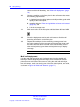
After the display value changes from 7 to 6, the cell boundary
is detected.
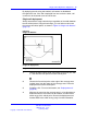
5 Record the cell boundary by marking a small X on the floor plan
where the cell boundary value was reached. Use a pencil that is
the same color as the critical point where the deployment tool
is located.
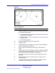
6 Repeat step 4 and 5 several times, walking in different directions
to determine where the cell center can be located and still
remain within range of the critical point.
7 Draw a thin contour line through the Xs to mark an arc on the
floor plan.
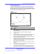
8 Choose the other critical point adjacent to the first critical point
and repeat steps 3 to 7.
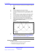
9 If the contour lines do not cross, or cross close to the edge of the
coverage area between the two critical points, see “Double cell
deployment” (page 75). Choose a position on the floor plan for
the cell center that meets the following requirements.
a is furthest from the critical points and still provides good audio
quality at the critical point
b complies with the “Rules and guidelines to locate cell centers”
(page 35)
c is in the coverage area
10 With a pencil, label the cell center on the floor plan with xCn.
The x is the floor, and n is the cell number in sequence of the
entire plan.
11 Place the deployment tool at each cell center to locate the cell
boundary.
12 Mark the cell boundary on the floor plan.
13 Repeat this task for the remaining coverage area from the
extremes of the coverage area toward the center until the entire
floor is been covered.
14 If the cell boundary covers any other critical points, ignore these
critical points as you proceed with coverage deployment.
Note: If it is not possible to place the basestation at the exact
crossover points of the arcs, place the basestation as close
as possible to the crossover.
--End--
Nortel Communication Server 1000
SIP DECT Fundamentals
NN43120-123 01.07
6 January 2009
Copyright © 2008-2009 Nortel Networks
.