
User's Manual
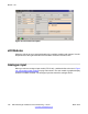
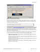
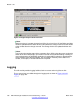
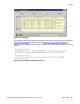

Figure 132: Analogue input ranges
Note:
Alarm values are given in pairs. Both maximum and minimum alarms are set and reset
with different values. This was implemented to prevent continuous switching between
set and reset when measured values are in the neighborhood of alarm values.
• Left-click in the status zone of an analogue contact to display the currently measured
value.
• If a measured value generates a maximum (+) or minimum (-) alarm boundary, the
Change area of the interface is updated.
Digital input (discrete input)
When you select a digital input module (FP-DI-300, FP-DI-301 or FP-DI-330), a window
appears similar to the one shown in
Figure 133: Digital Input module information on
page 185. For each module a graphical display shows the available contacts. A grey rectangle
indicates a discrete input value is Off, a green rectangle indicates a discrete input value is
On.
Module - eIO
184 DECT Messenger Installation and Commissioning — Book 1 March 2012
Comments? infodev@avaya.com