
User's Manual


104 DECT Messenger Customer Engineer Manual
database are filled in correctly after you use the eCONFIG module for
configuration.
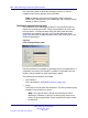
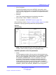
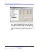
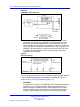
Figure 24 "Input/output relationships" (page 104) shows an example of
the relation between the input program and the output devices, and
uses the eIO Module as input module.
Figure 24
Input/output relationships
Figure 24 "Input/output relationships" (page 104) shows the settings in
the input module IO, and illustrates the relation between the contacts
(push buttons, switches) that are connected to the module. For
example, contact 01 under eIODI_Contact_str has the Group name
Fire1 in the column eIODI_GRP_str. Only eIODI_Group_ is shown in
Figure 24 "Input/output relationships" (page 104).
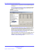
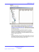
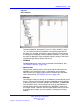
Under the eIO Module in the eCONFIG, two menus appear: Alarm and
Group. Under the Group menu, the groups that are specified in the
eKERNEL for that input module are displayed, as shown in Figure 25
"Groups in an input module" (page 105).
Nortel Communication Server 1000
DECT Messenger Fundamentals
NN43120-120 02.01
11 May 2009
Copyright © 2003-2009 Nortel Networks
.