Nortel Communication Server 1000 DECT Messenger Fundamentals Release: 6.0 Document Revision: 02.01 www.nortel.com NN43120-120 .
Nortel Communication Server 1000 Release: 6.0 Publication: NN43120-120 Document release date: 11 May 2009 Copyright © 2003-2009 Nortel Networks All Rights Reserved. Sourced in Canada LEGAL NOTICE While the information in this document is believed to be accurate and reliable, except as otherwise expressly agreed to in writing NORTEL PROVIDES THIS DOCUMENT "AS IS "WITHOUT WARRANTY OR CONDITION OF ANY KIND, EITHER EXPRESS OR IMPLIED.
. Contents New in this release Features 7 Other changes 7 7 Nortel DECT Messenger Administrator Guide 9 Preface 9 Nortel DECT Messenger overview 10 eCONFIG 18 Adding a DECT device to the Messenger system 51 DECT Messenger Customer Engineer Manual Preface 58 About the manual 58 Guidelines for maintenance and administration of a server or specialized computer 58 DECT Messenger overview 60 Nortel DECT Messenger functional description 60 Modules overview 62 Linking modules 65 DECT Messenger in a WAN o
eCAP 79 eESPA 79 eLOCATION 79 eSMS 79 eSNMP 79 eFR 79 Web administrator 80 What is required to run DECT Messenger 81 Hardware Requirements 81 Software Requirements 81 DMC Configuration 82 DATABASES in DECT Messenger 84 Supported Database types 84 How to set up the Databases 85 Installing and getting started 85 Stopping IIS WEB Services 85 Installing DECT Messenger 87 Getting Started 88 Using eCONFIG 95 Using eCONFIG (Local) on the DECT Messenger Server PC 96 Using eCONFIG (Remote) on remote PC (client) in
Configuring eSMTP_Server in eConfig 142 Configuring IIS for DECT Messenger 142 Using eSMTP 146 Sending SMS messages 147 eSMTP 147 eASYNC 147 V.24 - RS232 connections (eCAP, eESPA) 150 eCAP 151 eESPA 151 Using Import/Export menu 152 eLOG 153 “” (page 156) 156 OUTrqs.
Nortel Communication Server 1000 DECT Messenger Fundamentals NN43120-120 02.01 11 May 2009 Copyright © 2003-2009 Nortel Networks .
. New in this release Features There are no new features introduced with this release. Other changes For a detailed history of past releases of this document, see Table 1 "Revision history" (page 7). Table 1 Revision history May 2009 Standard 02.01. This document is up-issued to support Communication Server 1000 Release 6.0. October 2008 Standard 01.06 This document is up-issued to support Nortel Communication Server 1000 Release 5.
New in this release Nortel Communication Server 1000 DECT Messenger Fundamentals NN43120-120 02.01 11 May 2009 Copyright © 2003-2009 Nortel Networks .
. Nortel DECT Messenger Administrator Guide This chapter contains information on the following topics: • “Nortel DECT Messenger overview” (page 10) — “What is Nortel DECT Messenger” (page 10) — “Modules overview” (page 12) — “eCONFIG basic concepts” (page 14) — “DECT Messenger concepts” (page 16) • “eCONFIG” (page 18) eCONFIG Section — “Opening the eCONFIG” (page 18) — “eCONFIG main window” (page 20) — “Managing devices” (page 23) — “Managing groups” (page 32) — “Managing group members” (page 39)
Nortel DECT Messenger Administrator Guide For information about the other menu parameters in the eCONFIG module, or information for any of the other modules in Nortel DECT Messenger, refer to DECT Messenger Installation and Commissioning (NN43120-301). Nortel DECT Messenger overview DECT Messenger provides a software tool, the eCONFIG, for making changes to the configuration. The eCONFIG is on either the same PC as the DECT Messenger software, or on another PC in the TCP/IP network.
Nortel DECT Messenger overview • Analogue voltage/current levels: this form of message generation is used to guard industrial equipment. For example, equipment output messages can indicate pressure, temperature, and so on. • • Web interface from which you generate messages manually. 11 Programs you write that communicate (using TCP/IP socket) with DECT Messenger: DECT Messenger provides a port on TCP/IP that is open to receive input data from this type of unique program.
Nortel DECT Messenger Administrator Guide Modules overview DECT Messenger consists of separate modules. There are three main groups of modules: • • • Core software modules Input and output modules Security modules The following sections provide an overview of the modules. Detailed module descriptions are provided in DECT Messenger Installation and Commissioning (NN43120-301).
Nortel DECT Messenger overview 13 Table 2 Incoming and outgoing Modules (cont’d.) Module Name Function Incoming eIO Digital and analogue inputs and digital outputs (contacts and switches). Yes, analogue levels and digital levels (contacts) Yes, switches eWEB Web interface. Yes - eSMTP-server Receiving e-mail messages. Yes - eSMTP (client) Sending e-mail messages. - Yes eDMSAPI Sending and receiving E2-DECT messages using the CSTA interface.
Nortel DECT Messenger Administrator Guide assumes that the system is down and restarts the PC or activates an alarm indication. • eTM The eTM is a background module that automatically detects when another DECT Messenger module is down and restarts it. eCONFIG basic concepts The system configuration is stored in a database. You use the eCONFIG module to make changes to the configuration. This section explains how the eCONFIG module uses the database.
Nortel DECT Messenger overview 15 After you make changes in Users, Groups, or Devices, the changes are saved in the eCONFIG database, as well as in the operational database, and so are immediately activated. Note 1: If you make changes in the database copy that resides in eCONFIG, ensure that no one else is making changes in the operational database. If there are other pending changes, an error can occur after you shut down the eCONFIG and try to write the database into the DECT Messenger directory.
Nortel DECT Messenger Administrator Guide After you make changes in Users, Groups, or Devices, these changes are stored in the eCONFIG database on your PC. The changes are also immediately stored in the operational database on the DECT Messenger (server) PC and are, therefore, immediately active. Note 1: If there is more than one eCONFIG active at the same time, on different PCs, the individual eCONFIG databases are not updated/synchronized after a user makes a change in one eCONFIG.
Nortel DECT Messenger overview 17 identifier determines the final destination. The incoming group identifier must match a group identifier in the Groups functional block, which contains one or more output destinations (that is, the group members). The group members are the devices assigned to a Group. Figure 5 "eCONFIG" (page 17) shows the main window of eCONFIG with an example of an input module (the application programming interface [eAPI]).
Nortel DECT Messenger Administrator Guide The group identifier that originates at the input module determines the group to which the alarm must be sent. In “eCONFIG” (page 18), the group identifier is 00001. The group identifier can be a group name or any string of characters. • Group Member -- Device The group is composed of group members, and each group member is an actual device (for example, an Ergoline, a DECT handset, or an e-mail address).
eCONFIG 19 appears in the Windows task bar to indicate that the eKERNEL is running. If other modules are also running, an icon is displayed for each (for example, the eDMSAPI). 3 Start the eCONFIG. Double-click the eCONFIG icon on the PC desktop. 4 Enter your login information. The log in dialog box appears: Log in with the username and password provided by your system manager. If you are the system manager, and you have not changed any usernames and passwords yet, log in with the default login.
Nortel DECT Messenger Administrator Guide Note: The eCONFIG asks you which database you want to use. Ensure that you read the information on database handling in “eCONFIG basic concepts” (page 14) before proceeding. You have two options for database selection: 6 • Click YES: the eCONFIG uses the database that is still available in the eCONFIG module from a previous session. This database can be an old database.
eCONFIG 21 Figure 6 eCONFIG main window Note: The contents of the eCONFIG window are different for each user or for each system configuration. “eCONFIG main window” (page 20) shows all the menu items that are possible. The following menu items are available: • Import/Export menu: provides the option to import configuration data into tables in the configuration database, or to export configuration data from the configuration database tables. The file type is .csv.
Nortel DECT Messenger Administrator Guide • Areas: indicates the subdivisions in a site. Areas are used only if you have a connection from your DECT Messenger to more than one DECT Mobility Card (DMC) with DECT. For each connection from your DECT Messenger to a DMC system or an IP DECT system, you must specify a different area. Use a number to identify the area. The area number is used in the various modules in DECT Messenger. Note that in almost all installations you have only one area.
eCONFIG 23 Managing devices The following sections provide information that explain the following DECT Messenger tasks: • • • creating a new device changing the parameters of an existing device editing device parameters The following are examples of device types in DECT Messenger: • • • • • DNR in the DMC Directory Number (DN) in SIP DECT e-mail address cell phone number (for SMS) relay contacts You must know the properties of each device type relative to the equipment that hosts it (that is, device
Nortel DECT Messenger Administrator Guide 3 Set parameters for the new device. Note the following when setting parameters: • A red bullet before an item indicates that the item is mandatory. • • Some items contain default parameter values. Nortel recommends that you use the Browse option, when present, to define a location, rather than typing an entry. The parameters are described in “Device parameters” (page 27). 4 Confirm your choices. Click OK and follow the instructions on screen.
eCONFIG 25 Select All Groups from the Groups and Devices menu, or Group from the input module menu of your choice. --End-- Changing device parameters Complete the following steps to change device parameters. Procedure 3 Changing device parameters Step Action 1 Access the eCONFIG Groups and Devices menu. • • 2 Open eCONFIG. Expand the Groups and Devices menu by clicking the + to the left of it. Open the All Devices information window. Left-click the All Devices parameter.
Nortel DECT Messenger Administrator Guide 4 • In the right panel, browse in the list of devices in DECT Messenger. • Double-click the device that you want to edit. The Properties window of the device opens: Change the parameters. Click the name of the property you want to change. If you edit the parameters, note the following: • You cannot change the Output Program, the Site ID, the Area ID, or the Device ID.
eCONFIG 27 Device parameters As in previous sections, you can specify the following parameters for a device: • Output Program This field specifies the output program that processes a request. A device can be defined in more than one module. The indicated application threads the message using the capabilities of the infrastructure. The eDMSAPI can, for example, send E2 messages (non-voice-call to extensions such as DECT C4050 and C4060).
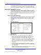
Nortel DECT Messenger Administrator Guide Figure 7 Select Output Program browser window • Device ID The device ID is the actual identifier of the device in the output equipment. Device ID consists of and delimited with #. For example, 04#01. Table 3 Variable definitions Variable Definition A fixed length value, in the range of 01 to 32, which indicates the DMC card ID in a PBX.
eCONFIG 29 01 to 10). DMC card numbering in Expansion Cabinets/Chassis continues sequentially in the range 11 to 20. The following table illustrates Device ID numbering for a small system.
Nortel DECT Messenger Administrator Guide Table 6 Example device IDs • DMC Card installed in Device ID 2nd slot on Main Cabinet on CS1000M, handset is subscribed with index 01 02#01 7th slot of shelf 0 on CS1000E, handset is subscribed with index 123 08#123 14th slot of shelf 1 on CS1000E, handset is subscribed with index 03 31#03 Output program facility The indicated application threads the message using the capabilities of the output device.
eCONFIG 31 the same or another extension. To reset the alarm using eDMSAPI (IC), the CLI of the calling extension must be entered here as the pincode. • Priority Reserved for future use. • Retry count alternative device Retry count alternative device defines how many times the application tries to deliver the message before switching to an alternative device (if one is defined in the list of Alternative Devices in the Groups and Devices menu). The default value is 30.
Nortel DECT Messenger Administrator Guide • Remote access site The Remote access site parameter is only applicable when you have more than one site, and you are using the web interface. A web server (eWEB) and a device are each assigned to only one site; if both are assigned to the same site, you can see the device from the web interface. Devices assigned to sites other than that to which the web server is assigned are only visible if the Remote access site parameter is set to True.
eCONFIG 33 3 • Expand the input module for which you want to create a new group. The instances (eAPI - area Area 1 in this example) of the input module are displayed. • Expand the instance. The submenu items Alarm and Group are displayed. • Expand Group to view all the groups for this instance of the input module. • Right-click the Group parameter. A pop-up menu opens. Create the new group and set the parameters. • • Select New Group from the Group pop-up menu.
Nortel DECT Messenger Administrator Guide • A red bullet before an item indicates that the parameter is mandatory. • • Some items contain default parameter values. Nortel recommends that you use the Browse option, when present, to define a location, rather than typing an entry. Note 1: The group name that you enter must match the group name entered for the input module. If the input module is an eAPI, eCAP, or eESPA, the group name matches that in the external system.
eCONFIG 35 • Expand the input module for which you want to create a new group. The instances (eAPI - area IBS 1 in this example) of the input module are displayed. • Expand the instance. The submenu items Alarm and Group are displayed. • Expand the Group item to view all the groups for this instance of the input module. • Right-click the Group parameter. A pop-up menu opens. Note: This illustration shows the eAPI input module. • 4 Select Open. The Group Properties/Parameters window opens.
Nortel DECT Messenger Administrator Guide 5 Confirm your choices. Click OK and follow the instructions on the screen, if applicable. --End-- Deleting a group To delete a group, follow “Changing group parameters” (page 34); at Step 4, click the Delete button. DECT Messenger asks you to confirm the action. After you confirm the action, the group is deleted immediately.
eCONFIG 37 paging number, group, or destination. In most cases, the group names are determined by third-party vendors and cannot be changed. Note: You can use the same group name for more than one input program. You can use the same group name because the DECT Messenger software adds the input program ID to the group name, which makes the group ID unique. This group ID is created automatically after you create the group. However, you can change the group name later. The Group ID remains the same.
Nortel DECT Messenger Administrator Guide Figure 9 Group members window The section “Changing group member parameters” (page 42) provides information on assigning new members, editing members, and deleting members. • Group authority The Group authority field defines which users are granted access to the group to make changes using the eWEB interface, or to use the eCONFIG. If you specify ALL, all users have access to this particular group, and you do not need to enter all individual users.
eCONFIG 39 Figure 10 Group authority Click the New button to give a new user the authority to make changes in the group. Click the Edit button to edit a user authority. WARNING If you want to delete a user from this group, do not click Delete in the window shown in Figure 10 "Group authority" (page 39), because that deletes the entire group. Instead, click Edit. A window specifically for that user opens. Click Delete in this window to remove the user from the group.
Nortel DECT Messenger Administrator Guide Procedure 6 Assigning a new member to a group Step Action 1 Open eCONFIG. Ensure that the member that you want to assign to the group is already in DECT Messenger as a device. (A group member is a device that is assigned to a group.) If the member does not exist as a device, see “Creating a new device” (page 23). 2 Access the Group Properties window.
eCONFIG 41 3 Open the Group members window. Click the >>>Group members item. A list of group members displays (the example shows only one group member: device 1010). 4 Add a new member. • Click New. The following window opens. Nortel Communication Server 1000 DECT Messenger Fundamentals NN43120-120 02.01 11 May 2009 Copyright © 2003-2009 Nortel Networks .
Nortel DECT Messenger Administrator Guide • • Click the Device ID menu item. Use the Browse button to select the device that you want to add as a member to the group. Note: After you select a device, the area and output program are defined automatically for the member. For more information on the parameters, see “Member parameters” (page 44). 5 Confirm your choices. Click OK and follow the instructions on the screen, if applicable.
eCONFIG 43 In the right panel of the window is a list of one or more group members that are assigned to the group. Select the group member that you want to edit, and click Edit. 3 Change the parameters. A window, similar to the one in Step 4 of “Assigning a new member to a group” (page 39), opens, however all parameters are entered. • Click the item you want to change. Note: You can change all parameters except the group ID and the parameters for device ID. 4 Confirm your choices.
Nortel DECT Messenger Administrator Guide Member parameters Member parameters are parameters that are added to a device for a specific group. These parameters are only applicable for the combination of a device and a group, and can be different after the same device is assigned to another group. The following parameters can be specified for a group member: • Group ID The Group ID field defines a unique identifier for a group.
eCONFIG 45 This value is a Boolean value: True or False. After set to True, the member is active on that day. • Holiday This value is a Boolean value: True or False. After set to True, the member is to be present on holidays. The holidays are defined in the Holiday parameter of the eCONFIG menu. • Activate Timestamp The Activate Timestamp value specifies the time after the member record is activated. The timestamp is formatted as follows: YYYYMMDDHHMMSS (for example: 20010101000000).
Nortel DECT Messenger Administrator Guide Procedure 9 Create a new user Step Action 1 Open eCONFIG. 2 Expand the All Users menu. Note: Two submenu items are listed: eWEB and eCONFIG. eWEB contains the users for eWEB, while eCONFIG contains the users for eCONFIG. These are separate from each other, however the approach and authority mechanism is the same, so the steps in this section apply to both. 3 Access the pop-up menu. In the All users menu, right-click either eCONFIG or eWEB.
eCONFIG 47 The parameters are explained in “User parameters” (page 49). 6 Confirm your choices. Click OK and follow the instructions on the screen, if applicable. --End-- Changing user properties The following procedure describes how to change the properties for user. Procedure 10 Changing user properties Step Action 1 Open the Group Members window. 2 Expand the All Users menu. Two menu items are available: eWEB and eCONFIG.
Nortel DECT Messenger Administrator Guide 5 Change the parameters. Change the parameters by clicking the item and changing the field contents. The parameters are explained in “User parameters” (page 49). 6 Confirm your choices. Click OK and follow the instructions on the screen, if applicable. --End-- Deleting a user The following procedure describes how to delete a user. Procedure 11 Deleting a user Step Action 1 Open the User Properties window.
eCONFIG 49 User parameters The following parameter descriptions are applicable for the parameters for both eWEB and eCONFIG users. • User ID This is the username that must be entered in the login dialog box. Maximum length is ten characters. Nortel recommends that you create a user profile for each user who has access to the eWEB interface. Sharing user profiles can result in unauthenticated users, which generates alarms.
Nortel DECT Messenger Administrator Guide This is a text description of the user, and is for administrative purposes only. The real name of the user is often stored in this field. • Language You must enter a four-digit code representing the language for the eWEB module. For the eCONFIG you must fill in a two-character representation for the language (for example, EN represents English). If you make a mistake, only menu icons are displayed, and not the menu items.
Adding a DECT device to the Messenger system 51 The e-mail address field contains the e-mail address of the user. After the user sends an e-mail using the web interface (Send SMTP Message menu), this e-mail address is used in the From: field (that is, the originator address). • All object authority The user can maintain all groups in DECT Messenger with the All object authority parameter. Remember that a user can be assigned to a group.
Nortel DECT Messenger Administrator Guide Procedure 12 Adding a DECT device to the Messenger system Step Action 1 Configure a device format. Ensure that you have a Device Format for this type of DECT handset. For information about configuring device formats, refer to DECT Messenger Installation and Commissioning (NN43120-301). Browse to Groups and Devices > Device Format.
Adding a DECT device to the Messenger system 53 For more information about Device ID, see “Device parameters” (page 27) 4 • Configure the Output Program Facility according to the type of DECT handset you have. Example: C4050 • Visual DNR The Directory Number (DN) of the DECT handset. Example: 2947 • Description Add a description of the handset. This can be the name of the handset owner. Example: Emmett Lee This description is displayed on the eWeb ’Send DMS-API Message’ Extension box.
Nortel DECT Messenger Administrator Guide 7 • Group Members. Click New. Browse under Device_ID for the device you created in Step 2. • Group Authority. Click New. Under User_ID browse for *ALL Open the Inbound data call handling menu. • In eConfig, open the menu Modules, and expand the eDMSAPI module by clicking the + beside it. Under the eDMSAPI module, the instances of the input module (For example, eDMSAPI - area One) are listed.
Adding a DECT device to the Messenger system • • • • Click New • Alarm ID for urgent messages: Browse and select the alarm E2_MSG_U Called device: Enter the DN of the DECT handset Calling Device: *ALL Alarm ID for normal messages: Browse and select the alarm E2_MSG_N Make the following configuration changes for Inbound Result: • • • • Click New • Message: [msg] [Calling number] Called device: Enter the DN of the DECT handset Calling Device: *ALL Group name: Browse and select the Group you created
Nortel DECT Messenger Administrator Guide Nortel Communication Server 1000 DECT Messenger Fundamentals NN43120-120 02.01 11 May 2009 Copyright © 2003-2009 Nortel Networks .
. DECT Messenger Customer Engineer Manual This chapter contains information on the following topics: • • • • • • • • • • • • • • • • • • • • • “DECT Messenger overview” (page 60) “Modules overview” (page 62) “DECT Messenger in a WAN or MAN network” (page 68) “Licensing” (page 69) “Detailed module descriptions” (page 73) “What is required to run DECT Messenger” (page 81) “DATABASES in DECT Messenger” (page 84) “Installing and getting started” (page 85) “Using eCONFIG” (page 95) “Using eTM” (page 98) “
DECT Messenger Customer Engineer Manual Preface This chapter is for Nortel DECT Messenger version 4.0, and is designed to be used in conjunction with the information found in other chapters. This chapter describes the steps necessary to configure and begin using the system. It describes how various modules work, but does not go into detail. For detailed descriptions of modules and how they work, consult DECT Messenger Installation and Commissioning (NN43120-301).
Preface 59 3. Back up your data. All computers eventually fail (hardware or software), and after servers fail, the data stored on them is often lost. Keeping current backups of the system, and data stored on it, is essential for every production system (servers, specialized machines, and so on).
DECT Messenger Customer Engineer Manual A power failure is one of the most common problems in a server environment, and also one of the most dangerous, because power failures can cause data loss after the system shuts down without closing data files and applications. An Uninterruptible Power Supply (UPS) filters the current and, in the event of a general power failure, provides the system with enough power that the applications can close properly.
DECT Messenger overview 61 Message input The following input can generate messages in DECT Messenger: • ESPA 4.4.4 pager protocol: DECT Messenger can receive pager messages from ESPA 4.4.4-compatible pager equipment. • RS232/V.24 serial input: many protocols are supported as input for generating a predefined message or a free message. • DECT handset with E2 (Low Rate Messaging Services [LMRS]) messaging.
DECT Messenger Customer Engineer Manual Message length can be specified for each device type. Messages that are too long to be displayed are broken into sections suitable for the display devices. • SMS messages to cell phones DECT Messenger can send SMS messages to cell phones. The interface to the cell phone provider can be a modem, or a box that behaves like an actual cell phone with SIM card. This option is mainly used as an alternative device.
DECT Messenger overview 63 The eKERNEL is the core software in the system and must always be present. eKERNEL is between the incoming and the outgoing modules and must always be running. The system does not operate if eKERNEL is absent or non-functional. Configuration modules There are two configuration modules: • eGRID The eGRID module is used to make inquiries and to edit the configuration database. The configuration database (an MS Access database) stores all the configuration data.
DECT Messenger Customer Engineer Manual Table 7 Incoming and outgoing modules (cont’d.) Module Name Function Incoming Outgoing eSMTP (client) Sending e-mail messages - Yes eDMSAPI Sending and receiving LRMS (E2) DECT messages using the CSTA interface. Yes, receiving LRMS (E2) DECT messages Yes, sending LRMS (E2) DECT messages eASYNC Asynchronous modem interface to cell phone SMS provider, or to wide area paging system.
DECT Messenger overview • 65 eWATCHDOG The eWATCHDOG is a software module that works with the Watchdog card. The eWATCHDOG sends a code to a V.24 interface (COM port) on the DECT Messenger PC. This COM port is connected to a Watchdog card that expects the code within certain time intervals. If the code is not received within the time interval, the Watchdog card assumes that the system is down and restarts the PC or activates a alarm indication.
DECT Messenger Customer Engineer Manual Figure 12 Example of logical representation of module links Figure 13 Example of module links (practical) Nortel Communication Server 1000 DECT Messenger Fundamentals NN43120-120 02.01 11 May 2009 Copyright © 2003-2009 Nortel Networks .
DECT Messenger overview 67 In Figure 12 "Example of logical representation of module links" (page 66), four DECT Messenger modules are shown (eCAP, eKERNEL, eIO, and eDMSAPI). These modules are grouped around the eKERNEL. Each input/output module (eCAP, eIO, eDMSAPI) communicates with the eKERNEL through a socket. The default port numbers are shown in Figure 12 "Example of logical representation of module links" (page 66).
DECT Messenger Customer Engineer Manual Table 9 Site and Area structure Area Site Module To DMC 1 1 eDMSAPI 1 1 2 eDMSAPI 2 You can use this modular structure to do the following: • • • install modules on different computers in the TCP/IP network set up a standby eKERNEL on a second site connect more than one DMC to DECT Messenger DECT Messenger in a WAN or MAN network DECT Messenger can be used in a multiunit MAN (IMP network), or in a multinode WAN (DPNSS network).
Licensing 69 Figure 14 DECT Messenger in a multiunit or multinode environment Figure 14 "DECT Messenger in a multiunit or multinode environment" (page 69) shows a multiunit or multinode network. DECT Messenger must be able to send messages to DECT handsets in Unit X/Node X and Unit Z/Node Z. On the DECT Messenger computer (Area 1), the eKERNEL is running with other modules and an eDMSAPI to send messages to Unit X/Node X. The second computer (Area 2) provides messaging to Unit Z/Node Z.
DECT Messenger Customer Engineer Manual For each DECT Messenger link to a DMC, one application license is needed for the DMS (DMSAPI). DMS is needed for sending and receiving LRMS (E2) messages using the CSTA link. In addition to the application license, you must have seat licenses.
Licensing 71 Figure 15 DECT Messenger License Manager Note: Figure 15 "DECT Messenger License Manager" (page 71) also shows the CTI application as a licensed application. You require this CTI application license only if a connection exists to the DECT system. The following licenses are available through the License Manager: • Application module licenses These licenses allow you to use a limited set of functionality licenses.
DECT Messenger Customer Engineer Manual Equipment for which you can acquire licenses is as follows: — DECT Messenger eI/O — DECT Messenger eCAP — DECT Messenger ESPA444 — DECT Messenger eLOCATION — eSMS (with SMS_service) — eSNMP • Functionality licenses These licenses allow you to implement certain functionality. The functionality licenses are submitted to the PC application module licenses.
Detailed module descriptions 73 Figure 16 SOPHO CTI Module License Manager For each connection to a DECT system, you require a CTI application license. The number of CTI message channel licenses you require is the sum of the following items: • total number of simultaneous outgoing LRMS messages coming from the eKERNEL. • total number of simultaneous outgoing LRMS messages coming from the web interface. • total number of DECT handsets that can send LRMS messages to DECT Messenger.
DECT Messenger Customer Engineer Manual • • • • • • • • • • • • • • • “eIO” (page 75) “eSMTP” (page 75) “eSMTP_Server” (page 75) “eAPI” (page 76) “eWEB” (page 76) “eGRID” (page 78) “eTM” (page 78) “eLOG” (page 78) “eCAP” (page 79) “eESPA” (page 79) “eLOCATION” (page 79) “eSMS” (page 79) “eSNMP” (page 79) “eFR” (page 79) “Web administrator” (page 80) eKERNEL The eKERNEL module is the main module of the DECT Messenger application.
Detailed module descriptions 75 to one or more DMC units for eDMSAPI. If the DECT handsets are in more than one unit, you can use an eDMSAPI module on one PC, or you can install eDMSAPI modules on other PCs as well. The External Application Interface (EAI) – used for LRMS messaging with the web or external applications – supports normal, urgent and emergency messages. In previous releases the SNDEMSG was not available.
DECT Messenger Customer Engineer Manual on the e-mail address entered in the To: field. The alarm message appears in the Subject field of the e-mail. The e-mail can be empty, because the content is ignored. E-mail handling procedure in DECT Messenger After you send an e-mail message to DECT Messenger, the message enters at the SMTP port of the IIS SMTP Server. The IIS SMTP Server drops the message in a directory on the hard disk.
Detailed module descriptions 77 — Global System for Mobile Communications (GSM) phones using SMS — Switch on/off an alarm contact The eWeb server runs on an Apache web server; IIS web server is not supported. To access the eWEB application, a username and password are required. The eWeb module offers two interfaces: basic and advanced. Basic Using the eWEB Basic module you can send messages directly to a single device only.
DECT Messenger Customer Engineer Manual Advanced The eWeb Advanced application is an expansion on the eWeb Basic application. Use the advanced application to perform system management tasks using the web interface, and to use script messages for emergency situations. Use these system management tools when you need a quick overview of the configuration of the system, or to make changes to groups settings or composition. A Script message contains actions that must be taken in the event of an alarm.
Detailed module descriptions 79 eCAP The eCAP Module handles a V.24 interface. Over the V.24 interface, there can be many protocol variants. A number of protocols are predefined in the eCAP. For the latest list of supported protocols, refer to Module - eCAP in DECT Messenger Installation and Commissioning (NN43120-301), or check the most recent commercial documentation. You can use the eCAP_Generic module to set up your own protocol for incoming character strings using the V.24 interface.
DECT Messenger Customer Engineer Manual eFR performs the following: • • • monitors the DISK state and threshold level monitors the NETSTAT like connectivity (client/server) performs PING to check responsiveness on ICMP level Notification at begin and end condition is possible through various transport mechanisms, such as e-mail, SNMP, NET SEND and SMS.
What is required to run DECT Messenger 81 — Work with devices — Work with facilities • Expert maintenance — Import Template configuration Refer to Module - Web Administrator User Guide in DECT Messenger Installation and Commissioning (NN43120-301) for more information. What is required to run DECT Messenger Hardware Requirements The hardware requirements for DECT Messenger are grouped into mandatory requirements and optional requirements.
DECT Messenger Customer Engineer Manual — Windows 2000/XP Professional or Windows 2000/2003 Server. — If you decide to use MS SQL Server as the database engine, you must have Windows 2000/2003 Server. Windows 2000/2003/XP Professional is not supported for SQL Server. (MSDE is supported under Windows 2000/2003/XP Professional.) — Minimum required Service Package is SP4. — WINZIP to unzip the DECT Messenger files during installation. — Virus scanner, because your DECT Messenger is connected to a network.
What is required to run DECT Messenger The CSTA_Service provides the CTI link to the DMC. Connection to Multiple DECT Systems To connect to more than one DECT system you must have a CTI link for each DECT system. Check your license for the number of CTI links available to you. For each DECT system, you must configure a new eDMSAPI module instance. Each DECT System must be configured in a different Area, as shown in Figure 17 "Connecting to two DECT systems" (page 83).
DECT Messenger Customer Engineer Manual Table 10 Example: Connecting to two DECT systems PC 1: PC 2: License, Dongle, License Manager eDMSAPI module - Area 2 eKERNEL eCONFIG CSTA_Service (With at least 2 CTI links) eDMSAPI module - Area 1 DATABASES in DECT Messenger This section describes the databases used by DECT Messenger. Supported Database types DECT Messenger uses two databases: • Configuration Database In this database, all configuration data is stored.
Installing and getting started 85 The DECT Messenger eKERNEL and the eWEB modules have access to the database through ODBC. You must set up the ODBC link in the ODBC, which is described in Installing ODBC. — SQL Server This is the most extended type of database. SQL Server provides a user interface to perform Database maintenance. You must install the DECT Messenger database in MS SQL Server manually. MS SQL Server is a licensed product.
DECT Messenger Customer Engineer Manual If the Microsoft Internet Information Services (IIS) is installed in Windows, you must stop the IIS WEB Services, otherwise IIS conflicts with the Apache Server. Stopping the WEB services of IIS is described in Procedure 13 “Stopping WEB Services IIS for DECT Messenger” (page 86). Procedure 13 Stopping WEB Services IIS for DECT Messenger Step Action 1 Open the Internet Information Services (IIS) window.
Installing and getting started 87 IIS no longer starts the Web services. --End-- Installing DECT Messenger The software installation process is described in DECT Messenger Installation and Commissioning (NN43120-301) in the chapter General - Install PC. Procedure 14 Installation of DECT Messenger Software Step Action 1 Verify that the licenses and Options are set correctly in the DMC. 2 Verify that the CSTA link to the DMC is installed and operational. 3 Verify license availability.
DECT Messenger Customer Engineer Manual Getting Started After installation, you can start DECT Messenger by restarting the PC. “Getting Started” (page 88) provides the procedure to start using the system. Note: To load your license file you must first acquire the License file licxxxx.lic and the DECT Messaging USB Dongle Procedure 15 Getting Started Step Action 1 Install the dongle and start the License Manager.
Installing and getting started 3 89 Install a preconfigured database, if you have one. DECT Messenger already contains a configuration database with data. However you must adapt the data in the database to your needs. However, if you have a preconfigured database, specifically made for your system, you must install that database into the database directory, by carrying out the following steps: 4 • Open the following directory using the Windows Explorer: c:\SOPHO Messenger@net\mdb\.
DECT Messenger Customer Engineer Manual 7 • • Enter the Administrator name and Administrator e-mail. • Click OK. Enter the IP address of the PC where the eKERNEL resides in the field: eKERNEL IP Address. Check the Configuration database path. Still in the eCONFIG window, you must specify the database locations (the default database path are usually correct).
Installing and getting started 8 91 Check the Dynamic database path. eKERNEL must have a valid path to the dynamic data database (the default database path are usually correct). Determine which type of database you are using: MS Access, MSDE or SQL Server. The settings for MSDE and SQL Server in this window are the same as the settings in eCONFIG. • If you are using the MSDE or SQL Server database, ensure that you have set up the ODBC configuration for the eWEB correctly.
DECT Messenger Customer Engineer Manual • Set the path for the MSDE or SQL Server database: The path setting for the MSDE or SQL Server database must point to the ODBC link that you created after you installed the eWEB module. Note: The path setting for the MSDE or SQL Server database must be assigned as System DSN in ODBC. Before you continue, ensure that you know the username and password for the database. Normally the User ID (login name) for the database is sa, and the password is sa.
Installing and getting started 11 93 Enter configuration information. Enter the correct values for the IP addresses: Area Description - Description field for the DECT system you are connecting to. Seats Count - Total number of seats you require.
DECT Messenger Customer Engineer Manual • Expand the item Modules > eWEB Module. One instance of the eWEB module: eWEB - area is shown. • Double-click the eWEB instance to open the parameters/pro perties. Click IP addresses, as shown in Figure 18 "eWEB Properties" (page 95). The first line in the right pane contains the loop back address (127.0.0.1) of the PC. Do not change this. The second line contains the correct IP addresses. • • Select the second line, and click Edit.
Using eCONFIG 95 that the information in the list comes from the table: eKERNEL_DEVICE. • Click Enter to send the message. Verify that the message arrives at the extension that you have specified; if the message arrives, your DMS-API is working correctly. Now you can set up the other modules as needed. --End-- Figure 18 eWEB Properties Using eCONFIG The eCONFIG Module is the tool most commonly used for making changes in the configuration. The configuration is stored in a Database.
DECT Messenger Customer Engineer Manual Using eCONFIG (Local) on the DECT Messenger Server PC After the eCONFIG is installed on the DECT Messenger server PC the database is handled as shown in Figure 19 "Database handling with eCONFIG on the DECT Messenger Server PC (Local)" (page 96). Figure 19 Database handling with eCONFIG on the DECT Messenger Server PC (Local) After you start the eCONFIG for the first time, a copy is made of the configuration database of DECT Messenger (Messenger_CFG.MDB).
Using eCONFIG 97 database, as that causes an error if you try to shut down the eCONFIG and write the database back into the DECT Messenger directory. Note 2: If there are Monitored devices in the active configuration, and one of these devices initiates a follow-me, the diversion information is stored in the active database.
DECT Messenger Customer Engineer Manual After you start the eCONFIG for the first time on the remote PC, a copy is made of the configuration database of DECT Messenger (Messenger_CFG.MDB). This copy is stored on the remote PC where the eCONFIG is running, in the eCONFIG directory: C:\SOPHO Messenger@net\eConfig\Mdb with the file name: Messenger_WRK.cfg.
eDMSAPI Inbound 99 The registry is not filled in automatically. You must edit it manually, with the help of a registry file, which is generated after you close down the eCONFIG using the File > Exit menu. You can also create the registry files using eGRID, using the button Generate Registry files for eTM in the right-top corner of the interface. The registry files are stored in the following directory: C:\SOPHO Messenger@net\exe\ An example of the file name is as follows: eTM - Site 1 - Environment: LOCAL.
DECT Messenger Customer Engineer Manual Incoming Alarm (IA) from DMC Incoming Alarm is an LRMS (E2) message that is sent from an LRMS DECT extension to an extension number (DNR) in the DMC. However, the DECT handset from which the LRMS (E2) message is sent is monitored (IO Registered) by DECT Messenger. The message is delivered to DECT Messenger, instead of to the intended destination.
eDMSAPI Inbound 101 extension 2000. Therefore, all LRMS (E2) messages that extension 2000 sends are sent to DECT Messenger. • DECT Messenger checks the intended destination of the message. If that destination is in the Inbound configuration in the eDMSAPI module, the message is regarded as a valid call.
DECT Messenger Customer Engineer Manual The extension number to which the message is sent for IC can be a hardware-less Directory Number (DN) in the DMC. Note: A message sent from an IO registered DECT handset to another DECT handset uses DECT Messenger, with a Group-to-Group Member-to-Device structure. Parameters required to set an alarm The structure of DECT Messenger is based on five parameters that are required for generating an alarm. Those five parameters can come from the input device.
eDMSAPI Inbound • 103 Alarm Description The Alarm Description refers to the eKERNEL_Alarm table, which contains all the properties that are associated with that specific alarm, such as Priority, ringing time of an extension, the repeat interval time, and so on. • Message This is the actual message that is transferred to the device. • Remove After: *SENT, *RESET, *CALCULATE This is described in “SET/RESET structure” (page 108).
DECT Messenger Customer Engineer Manual database are filled in correctly after you use the eCONFIG module for configuration. Figure 24 "Input/output relationships" (page 104) shows an example of the relation between the input program and the output devices, and uses the eIO Module as input module.
eDMSAPI Inbound 105 Figure 25 Groups in an input module A Group name must match a Group name that comes from the input module. In this example, the Group name (Fire1) must match the Group name that is assigned to the input contact (01) in Figure 25 "Groups in an input module" (page 105). Under the Group name Fire1, two Members are listed, which are actual output Devices (Device 2000 and Device DO_02_01).
DECT Messenger Customer Engineer Manual Figure 26 Input contact 01 Figure 26 "Input contact 01" (page 106) shows an example of an input contact 01 in the Input Module eIO. The input contact 01 in the column eIODI_Contact_str is related to the alarm identifier Fire1 under the column eIODI_ALA_Descr_str. Therefore, if the contact is activated, the alarm Identifier Fire1 is sent to the eKERNEL. This also means that there must be an Alarm Identifier in the eKERNEL_ALARM table called Fire1.
eDMSAPI Inbound 107 Figure 27 Alarm identifier The Alarm Identifier, illustrated in Figure 27 "Alarm identifier" (page 107), is used as an Alarm Description, and contains properties for the alarm (for example, ringing time, repeat intervals, scroll intervals if messages are chopped). These properties determine, in part, how the alarm is displayed. Other properties include: priority of the alarm, message length, silence interval, and so on.
DECT Messenger Customer Engineer Manual An example of an Input Module that does not receive a message from outside is the eIO Module. In the eIO Module you must assign a message to a switch or button. Figure 28 "Message assigned to a button" (page 108) shows the message assigned to a button. Figure 28 Message assigned to a button SET/RESET structure The SET/RESET structure of alarms is complex; you can Set an Alarm and wait for a Reset, or you can Set an Alarm from an Input Module to a Device.
eDMSAPI Inbound 109 Figure 29 Sent Alarm structure In this figure, there is an input module that generates an alarm as a sent. Therefore, the alarm is sent to the eKERNEL, and stored in an alarm database (data table). Immediately after sending, the input module withdraws the alarm, so the alarm condition is only present in the database table, with a fixed reference to the device for which the alarm message is meant. If the device acknowledges this alarm, the alarm condition is removed from the database.
DECT Messenger Customer Engineer Manual Figure 30 SET/RESET Alarm Structure The input modules eCAP, eAPI, and eIO can generate a set/reset command. (eIO set/reset is explained in more detail later on in this document.) An acknowledgment from a device does not clear the alarm condition on that device in the database. Therefore, even if the call on the device is answered, the alarm is not reset.
eDMSAPI Inbound 111 sent) the alarm call is cleared on this Acknowledge. If a message is sent as an Urgent message, the alarm call is cleared after the second Acknowledge arrives. After the user presses the Delete or OK key on the handset, the message call is acknowledged. Figure 32 Acknowledge sequences for Normal and Urgent messages using DECT handsets For alarm handling, bear in mind the following when setting up the system: • • An alarm is set in a data table in the eKERNEL.
DECT Messenger Customer Engineer Manual — The device on which the alarm is set. Alarm is reset after the call is Acknowledged (LRMS [E2] messaging) — The Input Module from which the alarm was set (eCAP, eAPI or eIO). — An Incoming Confirmation call from eDMSAPI. • You can use the I/O to set an alarm using a push button. This is issued after the button is pushed, and is handled as a SENT alarm. The alarm cannot be reset by a push button. • The SENT, SET, and RESET commands: — SENT.
eLOCATION 113 Module with the same Alarm Identifier, however, with the properties: *RESET after *SENT. • After you receive an alarm through eAPI, the options shown in Table 11 "Options for alarm handling" (page 113) apply to alarm handling: Table 11 Options for alarm handling Field: set or reset Field: Remove after DECT Messenger action *set *sent Alarm processed as sent alarm. *set *reset Alarm set and waits for a reset. *set *calc System sets the alarm.
DECT Messenger Customer Engineer Manual • location of the handset is only retrieved after a short message is sent to the predefined extension number. In all other cases, no location information is retrieved. • requires an IP connection to a DAP Controller (DCC) in the SIP DECT environment • location detection only works on SIP DECT extensions eLOCATION can support configurations with more than 255 radios.
eLOCATION • [Location] = the contents of the eLOCRPN_Message_str field in the table eLOCATION_RPN • • • • [Location time] = current time 115 [Location date] = current date. [Calling number] = calling number. [Called number] = called number The destination group, the message, and the Alarm ID are used to dispatch the message to the appropriate destination(s). eLOCATION Module in eCONFIG The eLOCATION module is configured through eCONFIG.
DECT Messenger Customer Engineer Manual Protocol guarding. Always is 10 seconds. • Retry Count Retry counter for retrieving information from the DAP Controller. Default = 5. • Retry Interval Retry Interval time between retries. Default = 10 seconds. • Polling Interval Polling interval is the interval time between poling message to the DCC to check if the connection is still alive. Default = 60 seconds. • >>>Board Definition Refers to the table: eLOCATION_BOARD.
Connecting National Instruments modules 117 Figure 34 Rail with National Instruments FieldPoint IO Modules The various types of IO modules that are supported for DECT Messenger can be classified as control modules or I/O Modules. Table 12 "Overview of supported control modules" (page 117) and Table 13 "Overview of supported IO modules" (page 118) give an overview of these modules. Table 12 Overview of supported control modules Module Type Description Additional info FP-1000 Control Module with V.
DECT Messenger Customer Engineer Manual Table 13 Overview of supported IO modules Module Type Description Additional info AI-100 Analogue input Module 8 Analogue inputs, each can be set to one of the following ranges: 30V, 15V, 5V, 1V, 0-30V, 0-15V, 0-5V, 0-1V, 20mA, 0-20mA, 4-20mA. DI-300 Digital Input 8 discrete input channels. These inputs are sinking inputs for 24VDC. DI-301 Digital Input 16 discrete input channels. These inputs are sinking inputs for 24VDC.
Connecting National Instruments modules 119 Figure 36 "National Instruments Modules connected to DECT Messenger" (page 119) shows a configuration of three rails with National Instruments modules connected to a DECT Messenger. The three rails with modules are connected together through the RS-485 bus. Note: A multi rail configuration is not part of the standard product, and is only available on a Project basis.
DECT Messenger Customer Engineer Manual Hardware Installation Hardware installation is described in the documentation from National Instruments. Software Installation Note: Due to subsequent software releases, the contents of this section can differ slightly from your actual product. The software for the I/O modules is based on the industry standard OLE for Process Control (OPC) Server software.
Connecting National Instruments modules 121 Figure 37 Software Parts for the I/O modules The OPC Server software can be controlled by only ONE application only. Therefore, you can have either the eIO Module active OR the FieldPoint Explorer. Note: Do not forget to close down the FieldPoint Explorer before you start the eIO module. Conversely, do not forget to close down the eIO Module before starting up the FieldPoint Explorer.
DECT Messenger Customer Engineer Manual Click Start on the Windows task bar, and choose Programs > National Instruments FieldPoint 2.0 > FieldPoint Explorer. 3 Add a comm resource. Right-click FieldPoint to open the following menu: In this menu select Add a comm resource to this server.... The following window opens: Nortel Communication Server 1000 DECT Messenger Fundamentals NN43120-120 02.01 11 May 2009 Copyright © 2003-2009 Nortel Networks .
Connecting National Instruments modules 4 123 Configure the comm resource In the Comm Resources Configuration window, set the following: • Name Accept the default name (FP Res). • Port This is the COM port on your computer to which you have connected your V.24 interface from the FieldPoint FP-1000 module. • Baud Rate Communication speed over the V.24 line. Default this is 115200 b/s. The DIP switch settings associated with the speed are displayed.
DECT Messenger Customer Engineer Manual • Time-out (msec.) Time out counter on the V.24 communication. Accept the default (200 msec). Note: Do not close this window yet; proceed to the next step. 5 Search for connected modules • Click Find Devices This scans the FieldPoint Module address through the V.24 interface, and automatically detects that modules are connected. Click this button if you are sure that all the other settings in this window are correct. The following window is displayed.
Connecting National Instruments modules 7 Right-click the device you wish to edit. • • 8 125 Right-click a device. In the pop-up menu, select Edit this Device... Set channel configuration values. Click Configure channels. In the Channel configuration window that is displayed, enable the lines that you use, and select the correct settings (this depends on what you have connected to the channels). Click Apply, and then OK. 9 Edit the remaining devices.
DECT Messenger Customer Engineer Manual If you do not close FieldPoint Explorer, the eIO Module does not receive information from the FieldPoint modules. Note: Setting up the eIO Modules is described in Module-elO. --End-- Understanding Security features Session Guarding Session Guarding is applicable for the input programs eAPI and eCAP. Session Guarding checks to see if there is input on a regular basis. This assumes that the equipment that is connected to the V.
Understanding Security features 127 Figure 38 Berkshire Product Inc. Internal serial PC Watchdog The Watchdog card is designed to monitor PCs used in critical applications such as: File Servers, Voice Mail Systems, Internet Service Provider (ISP) systems, industrial applications, and so on. The purpose of the Watchdog card is to ensure the PC is always available; especially for systems that are not continuously monitored.
DECT Messenger Customer Engineer Manual Figure 39 Configuration of the Watchdog card Note: To use the reset and automatic startup, ensure that the Reset button signals the PC to restart, instead of signalling Windows to restart. If the reset button signals for Windows to restart, and Task Manager is running, Task Manager blocks the restart command. Watchdog Installation The following procedure describes how to install the Watchdog.
Understanding Security features • • 129 Disconnect the PC reset cable from the motherboard. Plug the cable onto the J3 header in the upper left corner of the Watchdog. The PC Reset connections are as follows: 3 Attach the reset cable. Plug the supplied reset cable onto J2 on the Watchdog board, and plug the other end onto the original reset header on the motherboard. 4 Install the Watchdog. Install the Watchdog in a free slot/bracket position. 5 Connect the power.
DECT Messenger Customer Engineer Manual 8 Configure the Watchdog • • Select the time period Select the COM port Note 1: If you followed the instructions in Step 1 of this procedure, you set the Watchdog timer to 30 seconds. Therefore, you must fill in a time period that is significantly lower than this value, for example, 8 seconds. Note 2: After selecting the COM port, keep in mind that other Modules use COM ports as well, such as eCAP, eESPA, eIO. 9 Verify correct operation.
Understanding Security features 131 See the following section, “Watchdog settings and indicators” (page 131), for additional information about the Watchdog card. --End-- Watchdog settings and indicators • LEDs Table 14 Top LED Indications Top LED Indication Meaning Flashing at 1 second ON - 1 second OFF This condition appears at power up of the PC for 2,5 minutes, to let the PC power up. Flashing at 350 msec. rate Watchdog operational. No alarm condition. Flashing rapidly at 100msec.
DECT Messenger Customer Engineer Manual Table 16 Switches 6 to 8. (cont’d.) • Switches 6-8 Delay Time OFF- ON-OFF 30 Seconds OFF- ON- ON 1 Minute ON-OFF-OFF 10 Minutes ON-OFF- ON 30 Minutes ON- ON-OFF 1 Hour ON- ON- ON 2 Hour COM Port Settings The Watchdog requires that the COM port on the PC be set to 1200 Baud, 8 Data Bits, No Parity Bit, and 2 Stop Bits.
Using eBackup 133 --End-- Using eBackup The eBACKUP module provides a means to back up files. Use the eBACKUP configuration to specify which files must be backed up, and in what directory to store the copies. Nortel Communication Server 1000 DECT Messenger Fundamentals NN43120-120 02.01 11 May 2009 Copyright © 2003-2009 Nortel Networks .
DECT Messenger Customer Engineer Manual Figure 40 The Backup window In the Path settings, you can specify fields that are filled in by the system: [weekday] 1 ... 7, where 1=monday up to 7=sunday [timestamp] for example, 20030930124506 [weekdayname] Monday ... Friday The eBACKUP Module is NOT a scheduler.
Using eBackup 135 Figure 41 Shortcut definition to eBACKUP Note: Figure 41 "Shortcut definition to eBACKUP" (page 135) shows only a part of the line. The whole line in the Target field of the shortcut is: C:\SOPHO Messenger@net\Exe\eBACKUP.exe / Path:C:\SOPHO Messenger@net /Log drive:C /Site:1 /Batch:Y • Scheduled, using Windows Scheduler If you want automatically created backups of files, you must use the Scheduler in Windows to start the Backup module.
DECT Messenger Customer Engineer Manual Step Action 1 Open the Scheduled Tasks wizard. Click Start on the Windows task bar, and choose Settings > Control Panel > Scheduled tasks > Add scheduled task. The Scheduled Task wizard is displayed. 2 Open the Scheduled Tasks window. In the Scheduled Task wizard, click Next. Now you are in the Window, where you must select a program. 3 Browse to the eBackup program. Use Browse to go to the eBACKUP.exe program in the C:\SOPHO Messenger@net\Exe\eBACKUP.
Setting up e-mail integration (eSMTP_Server/eSMTP) 137 Clear the field Run. Fill in the following string in this field: C:\SOPHO Messenger@net\Exe\eBACKUP.exe / Path:C:\SOPHO Messenger@net /Log drive:C /Site:1 /Batch:Y. Click OK to close the Properties window. 8 Select the file to back up. In the eCONFIG, module eBACKUP, select which file you want to back up. --End-- Setting up e-mail integration (eSMTP_Server/eSMTP) General DECT Messenger can both send and receive e-mail messages.
DECT Messenger Customer Engineer Manual This module is capable of receiving and handling e-mail messages. Figure 42 "Sending e-mail from client to DECT Messenger" (page 138) shows the path of an e-mail message from client to DECT Messenger. Figure 42 Sending e-mail from client to DECT Messenger In DECT Messenger, the eSMTP_Server works in cooperation with the Microsoft Internet Information Services (IIS). It is possible that other e-mail servers can be used instead of IIS, but they are not supported.
Using eSMTP Server 139 Figure 43 e-mail handling in DECT Messenger After an e-mail is sent from the e-mail client to DECT Messenger, the e-mail generally goes through an e-mail provider (through a server). In this e-mail Server, relaying must be switched on, otherwise the e-mail is not transferred to DECT Messenger. Also, the e-mail Server must know to which PC the e-mail message is to be sent.
DECT Messenger Customer Engineer Manual After processing the e-mail message, the eSMTP_Server puts the message in the directory C:\inetpub\mailroot\drop\processed. If the message cannot be properly processed, eSMTP_Server does not put the message in the processed directory, but in the directory C:\inetpub\mailroot\drop\error. Note: You do not need to create users in the IIS. IIS is used for incoming SMTP only. On incoming e-mail, no authentication check is done.
Using eSMTP Server 141 no x-receiver: field. Then the eSMTP_Server uses the field: To: <1010@messenger5.com> instead. • Subject: please call John The message please call John is sent as message to the destinations (devices). Because DECT Messenger uses IIS, you must install and set up IIS. If you are using Windows 2000 Server, IIS is installed automatically, and you only have to configure IIS. If you are using Windows 2000 Professional, you must install IIS separately, and then configure IIS.
DECT Messenger Customer Engineer Manual • In the Windows Components window, check the check box Internet Information Services. • • Click Next. Insert the Windows CD-ROM after the system asks for it. --End-- Note: After installing IIS, you must reinstall Windows 2000 Service Pack 4. Configuring eSMTP_Server in eConfig You can use the default settings for the eSMTP_Server module in eCONFIG. You must create a Group Name for each e-mail address you wish to associate with DECT Messenger.
Using eSMTP Server 143 Click Start on the Windows task bar, and choose Settings Control Panel > Administrative Tools > Internet Services Manager. 2 Disable the default ftp/web sites. • Expand the PC name to access the FTP, WEB, and SMTP services under it. • Right-click the Default FTP Site, and select Stop in the pop-up menu. • Right-click the Default Web Site, and select Stop in the pop-up menu.
DECT Messenger Customer Engineer Manual 4 • Expand Default SMTP Virtual Server, by clicking on the + sign in front of it. Two submenu items are shown: Domains and Current Sessions. • Right-click Domains (under Default SMTP Virtual Server), and select New > Domain in the pop-up menu. Specify the domain type. Select Alias, and click Next. 5 Set the domain name. Enter the domain name. If necessary, contact your system administrator to verify the domain name.
Using eSMTP Server 6 145 Verify the Domain Name list. After entering the Alias, the IIS window must look like the following example: Note: The name Alias in this window is an example. In your configuration a different name appears. 7 Set the Drop Directory path. • Right-click the PC name (in this example: PC75), and select Properties from the pop-up menu. The following window opens: Nortel Communication Server 1000 DECT Messenger Fundamentals NN43120-120 02.
DECT Messenger Customer Engineer Manual The Drop Directory field specifies a directory where IIS drops all incoming messages. • • Leave the default value in place. Click OK. --End-- Using eSMTP The eSMTP module behaves like an e-mail client such as MS Outlook Express. Therefore, you must enter the Domain name and IP address of the SMTP Server to which you send e-mail messages. Nortel Communication Server 1000 DECT Messenger Fundamentals NN43120-120 02.
Sending SMS messages 147 Sending SMS messages eSMTP Many Global System for Mobile Communications (GSM) Service providers have an SMTP gateway into their SMS Centre, either directly, or through a third-party company. Consult with your local GSM provider to see if this facility is available. They can provide you with an e-mail address and format. For example: A DECT Messenger user wishes to use a GSM handset as an alternative device to the DECT handset.
DECT Messenger Customer Engineer Manual Figure 45 Setup for sending SMS Messages (or Wide Area Paging messages) The connection between DECT Messenger and the GSM SMS provider is made through a modem connection using the PSTN. In DECT Messenger, you must specify the correct settings for this connection. In the eCONFIG, go to the eASYNC Module to change the settings; the window shown in Figure 46 "eASYNC settings" (page 149) opens.
Sending SMS messages 149 Figure 46 eASYNC settings The following overview explains the eASYNC settings: • Type The type is either SMS for SMS messages to GSM phones, or Paging for Wide Area Paging. • Provider This is the name of the (GSM) provider that provides the dial-in option for SMS or Wide Area paging. Note: This field only supports the following names: BELGACOM, PROXIMUS, and KPN: — BELGACOM refers to the Wide Area paging protocol.
DECT Messenger Customer Engineer Manual • Telephone Number The messenger must know what number to dial to access the provider. (This is not the extension number of the cell phone [GSM phone] to which the message must be sent.) As example, for PROXIMUS, this is number 00475161622. • Initialization string This is the initialization string for modem initialization. The string depends on the type of modem that you use. A generic modem initialization string can be for example: AT&C0S0=3.
V.24 - RS232 connections (eCAP, eESPA) 151 eCAP There are four different types of devices that can be connected to the eCAP module using V.24/RS232, as follows: • Nurse Call systems There are many types of Nurse Call systems offering data using V.24/RS232. However, there is no standard protocol. • Building Management systems There are many types of Building Management systems offering data using V.24/RS232. However, there is no standard protocol.
DECT Messenger Customer Engineer Manual Using Import/Export menu You can use eCONFIG to import and export configuration database tables. The menu options are shown in Figure 47 "Import/Export menu options" (page 152). Figure 47 Import/Export menu options The Import/Export function can only handle files of the type .csv. Double-click Export, to open the following window: Figure 48 The Export window In the left-top pane, a list of configuration database tables is shown.
eLOG 153 The files are stored in the following directory: C:\SOPHO Messenger@net eConfig\Csv Figure 49 The configuration file storage directory You can also import configuration database tables using the Import menu. You must ensure that the format of the .csv file matches the required format. To ensure that the format is correct, you can export the table as an example. Note: Ensure that the format and the contents of the .csv files are correct, before you start the import function.
DECT Messenger Customer Engineer Manual The eLOG module does not have a user interface and does not provide nice charts. However, it provides three *.csv files with detailed information indicating how the alarm was processed. Note: You must have sufficient technical knowledge of DECT Messenger to understand the contents of the files. The following three files are automatically created and updated: • INrqs.csv This file contains individual records for each alarm that came into the eKERNEL.
eLOG 155 Figure 50 eCONFIG module site menu In the menu option Path eLOG you can enter the path for the eLOG files. The menu option Number of Logging days is NOT applicable for the eLOG files. The eLOG files are never deleted by DECT Messenger. Therefore it can be wise to change the path to another drive on the same PC or to a network drive. This prevents the C drive from becoming overburdened with eLOG files. The logging information is written to a 1Kb buffer, instead of to the files.
DECT Messenger Customer Engineer Manual Figure 51 eKERNEL module refresh log file The contents of these files are related to each other by means of identifiers. You can import the files into a Spreadsheet application or Database Application of your choice, for further analysis. In the following sections, the contents of these files is explained. ALARM Remove After GROUP id GROUP Description DEVICE id DEVICE area DEVICE Outpgm eWEB user PINCODE Reason not processed “” (page 156) In the file INrqs.
eLOG 157 — msgrqs = Message request or also called incoming alarm — incrqs *IC = Incoming Confirmation • INPGM id The Input Program ID. Each input program has its own unique identifier. An Input Program ID is an identifier only, and the digits do not necessarily have a meaning, however, there the common convention is to use the digits as follows: Table 17 Default Input Program Identification.
DECT Messenger Customer Engineer Manual — Alarm Length as specified in the Alarm ID definitions. If the Alarm Length is set to 10 characters, only the first 10 characters of the original message are regarded as relevant and the remaining characters are stripped off. — Message Format as specified in the eVBVoice Settings of the Alarm ID in eCONFIG. The Message Format allows conversion of the original message. • MESSAGE Original This is the original message, as it came from the Input Program.
eLOG • 159 eWEB user Not yet implemented. • PINCODE After an incoming Confirmation is received, you see the PIN code in this field. (For an Incoming Confirmation, the TYPE filed shows incrqs *IC.) • Reason not processed This field gives you information on why an incoming alarm is not processed. The messages gives you a clear indication of the cause, such as an alarm cannot be processed. Another example of a message is: Called device does not exist in table eCSTA_INBOUND_EVENT. OUTrqs.
DECT Messenger Customer Engineer Manual Area of the output device to which the alarm was sent. • DEVICE Outpgm Output Program of the output device to which the alarm was sent. • DEVICE Outpgm Facility Output Program facility of the device to which the alarm was sent. Note that the Facility specifies the device type characteristics. • DEVICE Member status This field indicates the status of the member based on its presence.
eLOG • 161 DIVERTED DEVICE Area Area of the diversion destination device. • DIVERTED DEVICE Outpgm Output Program that is used for the diversion destination device. • DIVERTED DEVICE Outpgm Facility Output Program Facility that is used for the diversion destination device. “” (page 161) This file contains information about the response(s) (reply) that came from devices on an outgoing alarm/message. The following columns are available: • OUTRQS id This is a tag for each output request.
DECT Messenger Customer Engineer Manual • DEVICE Outpgm Output Program of the output device that generated the response. • DEVICE Outpgm Facility Output Program facility of the output device that generated the response. • MESSAGE This is the actual message that was send to the output device and for which it generated the response. • ALARM id This shows the ALARM id that was used for the outgoing message, on which the device generated the response.
eLOG 163 This is the status of the response. It can be an ACK^, NACK^ or ACK^NACK^. — ACK^ The device has sent an acknowledgement to confirm that the alarm was received by the device. Some devices send such an acknowledgement on receiving the message. Some devices only send an acknowledgement after the message is read by the receiving person. — NACK^ The device has sent a negative-acknowledgement to indicate that the device is unreachable.
DECT Messenger Customer Engineer Manual This parameter indicates whether the alarm call was diverted to an Alternative Device or not. After an alarm call is diverted, you see a -1 (True) on the original device and on the Alternative device. — -1 = Diverted to Alternative device — 0 = Not diverted to Alternative device • ALT DEV Id This parameter shows the destination device, in case an alarm call is diverted. Note that a device is not always unique by the Device id parameter on its own.
Checking diagnostics 165 to which devices the alarm/message was sent. You also know the most important parameters that were used to send the alarm/message. 6 Use the identifiers that you used in the previous steps: OUTRQS id, INRQS id, DATE, TIME and Message, to check the reply/response of the devices in the file OUTrpy.csv. This shows you if the device did receive the message, did respond to the message or if the message was diverted to an alternative device.
DECT Messenger Customer Engineer Manual Figure 52 Log file location The Table eKERNEL_SITE defines the directory where the log files are stored, and the number of days that the files are retained. The information in the log files is stored in XML format, as shown in Figure 53 "IO Module log file" (page 167). Nortel Communication Server 1000 DECT Messenger Fundamentals NN43120-120 02.01 11 May 2009 Copyright © 2003-2009 Nortel Networks .
Checking diagnostics 167 Figure 53 IO Module log file Figure 53 "IO Module log file" (page 167) shows the contents of a log file for the IO module. The subsequent XML strings are the result of pressing a button on the DI module, module 02, contact 01. As result of pressing this button, contact 01 is activated on the Digital Output module 03 for three seconds.
DECT Messenger Customer Engineer Manual • DI This tag indicates the type of message, which indicates that the message was generated by the Digital Input contact. • 02 This tag specifies from which module the message comes. In Figure 53 "IO Module log file" (page 167), the message comes from the second module. • 01 This tag indicates the contact on the IO module. • 1 This tag indicates the contact status.
Checking diagnostics 169 Module Window Each module runs as an application in the Windows environment, and can be displayed as an open window, or minimized on the Windows Task bar. The module window provides online information about settings, commands/messages/communication. This information is very useful for debugging. The eIO module is shown for the purposes of demonstration; other modules have a similar interface, however, the information displayed is unique in each application.
DECT Messenger Customer Engineer Manual Figure 55 eKERNEL Tab The Jobq pane shows the pending jobs for the module. In the Outq pane, the outgoing communication from the module is shown. • eIO Tab The eIO tab shows IO module specific information. Figure 56 eIO Tab • Connections Tab The Connections tab shows information on the connections between the eIO module and the eKERNEL. This tab also shows information on the connections between the external part and the eIO module itself.
Checking diagnostics 171 Figure 57 Connections Tab The right pane gives information about the external devices that are connected to the eIO Module. The left pane shows information about the TCP/IP connections. The connections between the eKERNEL and the eIO module are shown in the top part of the left pane. The connections between the IO module and (if applicable) an external device are shown in the bottom part of the left pane.
DECT Messenger Customer Engineer Manual Figure 58 Status lamps In the bottom part of the left pane, two lamps are visible, indicating the status of the TCP/IP connection. The left lamp indicates the status of the connection between the IO module and the eKERNEL. The right lamp indicates the TCP/IP status between the IO module and the external device (if applicable). Both are green in Figure 58 "Status lamps" (page 172).
Checking diagnostics 173 eKERNEL Window The window of the eKERNEL differs from the other modules, and has a tab for each individual module. Figure 59 eKERNEL module window Select a module tab to see the information for that specific module, as follows: • TCP status. Shows the connection data for the TCP/IP connection between the eKERNEL and the module. • • Client information Shows information about the module. • Detail. Shows communication.
DECT Messenger Customer Engineer Manual The bottom of the eKERNEL window shows all the commands going to or coming from the eKERNEL. Simulation Options in a Module You can use a simulation menu in modules to simulate an message. The simulation is different for each individual module, because the nature of the modules differ. Figure 60 "Accessing Simulate Options" (page 174) shows you how to access the simulation menu.
. Index A D ACK 108 Adding a DECT device 51 ALARM Description 156, 159, 161 ALARM id 156, 161 Alarm properties 17 ALARM Prty 156, 159, 161 ALARM Remove After 156 Alarms 16, 153 ALT DEV Area 161 ALT DEV id 161 ALT DEV Outpgm 161 ALT DEV Outpgm Facility 161 Assigning a new member to a group 39 Automatic Watchdog startup 132 Databases 84 DATE 159, 161 DECT device 51 DECT Messenger alarms 16 DECT Messenger concepts 16 DECT Messenger customer engineer manual 57 DECT Messenger defined 10 DECT Messenger f
E-mail handling 76, 138 E-mail integration 137 eAPI 12, 63, 73, 76 eASYNC 12, 63, 147 eBACKUP 13, 133 eBACKUP eGUARDIAN 64 eCAP 12, 63, 73, 79, 150–151 eCONFIG 12, 14, 18, 63, 78, 95, 115 eCONFIG - restarting (local) 15 eCONFIG - restarting (remote) 16 eCONFIG main window 20 eCSTA 73 eDMSAPI 12, 63, 73–74 eDMSAPI inbound 99 eESPA 12, 63, 73, 79, 150–151 eFR 73, 79 eGRID 63, 73, 78 eGUARDIAN 13 eIO 12, 63, 73, 75 eKERNEL 12, 62, 65, 73–74, 126 eKERNEL service options 174 eKERNEL window 173 eLOCATION 12,
Incoming modules 12 INPGM Appl 156 INPGM id 156 INPGM manufacturer 156 Input and output modules 12 Input device 156 Input module 17 INRQS id 156, 159, 161 INrqs.
SMS 147 SMS messages 147 software installation 120 Software requirements 81 SOPHO CTI module 72 SOPHO CTI module licenses 72 STATUS CONFIRMED 161 Stopping IIS WEB services 85 Supported control modules 116 Supported database types 84 Supported IO modules 116 SWITCH TO ALTERNATIVE 161 Switches 131 T TIME 159, 161 Trace history 165 Tracing the roll out of an alarm 164 U User parameters 49 User properties 47 Users 48 Using eBACKUP 133 Using eCONFIG 95 Using eCONFIG (local) 96 Using eCONFIG (remote) 97 U
Nortel Communication Server 1000 DECT Messenger Fundamentals Copyright © 2003-2009 Nortel Networks All Rights Reserved. Release: 6.0 Publication: NN43120-120 Document revision: 02.01 Document release date: 11 May 2009 To provide feedback or to report a problem in this document, go to www.nortel.com/documentfeedback. www.nortel.