Telephone Paging Amplifier 10-Watt Model Installation and Use Manual Issue 1, October 1999 © 1999 Bogen Communications, Inc. All rights reserved.
© 1999 Bogen Communications, Inc. All Rights Reserved. Printed in Korea. Notice Every effort was made to ensure that the information in this guide was complete and accurate at the time of printing. However, information is subject to change. Important Safety Information Always follow these basic safety precautions when installing and using the unit: 1. Read and understand all instructions. 2. Follow all warnings and instructions marked on the product. 3.
Contents Page INTRODUCTION ..........................................................................................................................4 PACKAGE CONTENTS..............................................................................................................4 INSTALLATION..............................................................................................................................5 Mounting ...................................................................................
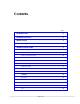
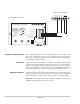
Telephone Paging Amplifier CAUTION: REPLACE CIRCUIT BREAKER WITH SAME TYPE AND RATING LUCENT TECHNOLOGIES NIGHT BELL VOL PEAK LEVEL PUSH TO RESET CIRCUIT BREAKER TONE LO-CUT 120 VAC 60 Hz 0.5A UL LISTED 538C COMMERCIAL AMPLIFIER COM 8 25V MUSIC VOL NIGHT TEL MUSIC GND BELL CONT IN 70V PAGE VOL TEL R T E15903 MADE IN KOREA Figure 1: Telephone Paging Amplifier Introduction This document describes the Lucent 10-watt Telephone Paging Amplifier.
Installation Mounting The amplifier is designed for wall mount applications. The 10-watt amplifier weighs 4 lbs. NOTE: The amplifier will produce heat during operation which will rise and may cause problems for temperature-sensitive equipment mounted above it. Mount the amplifier near the top of the backboard so that no other equipment will be above it. If this is not possible, then allow at least 12" between the top of the amplifier and the bottom of any equipment positioned above it.
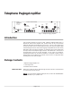
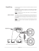
Telephone Paging Amplifier NIGHT TEL MUSIC BELL CONT IN GND Figure 2: Wiring for TEL Input TEL R T Universal Paging Access Module BGM IN MODE OFF 24VDC PWR SUPPLY 48VDC PWR SUPPLY CONFIRMATION TONE PREANNOUNCE TONE VOX DISABLE VOX ENABLE S1,S2 S3 S4 S5 ON S1,S2 PHONE SYSTEM S4 S3 EXT VOX ENABLE PAGING OUTPUT S5 CONTACT CLOSURE A PAGE PORT INPUT POWER SUPPLY (TRUNK ACCESS ONLY) T R +M -M PT PR N.O. COM +24/48 -24/48 (0.1A) MIN MAX TONE VOL.
Output Wiring All output wiring connections are made to the terminal strip located on the left side of the LU10WAMP. IMPORTANT: Before making any connections or wiring changes to the amplifier or any equipment connected to the amplifier, make sure that the amplifier is NOT plugged into an AC outlet. NOTE: The amplifier does not have a power switch, so it must be unplugged in order to turn the power off.
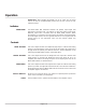
Operation IMPORTANT: Before plugging the amplifier into an AC outlet, turn all volume controls to their full counterclockwise positions and all other controls to their reference position. Indicator PEAK LEVEL The PEAK LEVEL LED illuminates whenever the speaker output signal level approaches its maximum level. This indicator is used when setting volume levels. Maximum output level is achieved when the PEAK LEVEL indicator flashes intermittently on loud peaks of the input signal.