
Configuration manual

Procedure
1. Attach the serial cable between the PC and the DTE port on the control unit.
2. Start the terminal program on your PC.
Note:
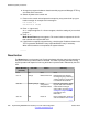
Ensure that the DTE port settings are configured as described in
RS232 DTE port
settings on page 232. Within a HyperTerminal session, the current settings are
summarized across the base of the screen.
3. Arrange the program windows so that the terminal program and Manager TFTP log
are visible at the same time.
4. Switch off power to the control unit.
5. Power on the control unit and press the escape key every second until you get a
loader message. An example of this message is:
P12 Loader 2.4
CPU Revision 0x0900
6. Enter AT (upper case).
An OK response appears. If OK does not appear, check the settings of your terminal
program.
7. To erase the backup configuration stored in non-volatile memory, enter AT-X2.
An OK response appears.
8. To erase the current configuration in RAM memory, enter AT-X3
A series of OK responses appear.
9. Switch power to the control unit off and then back on.
Messages appear as the control unit performs the start-up tasks.
10. Close the terminal program session.
11. Use Manager to edit and then upload an old configuration file or receive and edit
the system's now defaulted configuration.
About erasing the operational firmware
When the firmware loaded by the control unit is erased, the control unit begins making BOOTP
requests for a replacement firmware file. Manager can act as a BOOTP server and respond
to the control units request with the appropriate file from those installed with Manager.
When the firmware loaded by the B5800 Branch Gateway control unit is erased, the control
unit will first look for replacement firmware on the System SD card before falling back to using
a BOOTP request to Manager.
DTE port maintenance
Implementing B5800 Branch Gateway for a CS 1000 Configuration October 2012 237