FPC-08R1 8" SVGA TFT RISC Panel PC with FreeScale IMX51 Quick Reference Guide 1st Ed –1 April 2013 Copyright Notice Copyright 2013 Avalue Technology Inc., ALL RIGHTS RESERVED. Part No.
FPC-08R1 CONTENT 1. Getting Started ............................................................................................................ 3 1.1 1.2 1.3 1.4 2. 1.4.1 Front & Top View ......................................................................................................................... 5 1.4.2 Right Side View ............................................................................................................................ 5 1.4.3 Left Side View ....................
Quick Reference Guide 1. Getting Started 1.1 Safety Precautions Warning! Always completely disconnect the power cord from your chassis whenever you work with the hardware. Do not make connections while the power is on. Sensitive electronic components can be damaged by sudden power surges. Only experienced electronics personnel should open the PC chassis. Caution! Always ground yourself to remove any static charge before touching the CPU card.
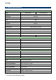
FPC-08R1 1.3 System Specifications Panel FPC-08R1-M51 Model FPC-08R1-M51W 8 inch LCD size SVGA TFT Display type 800(R.G.B) x 600 Resolution 262K Color Pixel pitch 0.0675mm(W) x 0.2025mm(H) Luminance 250cd/m² Contrast ratio 400 Viewing angle 50(U), 70(D), 70(L), 70(R) Response time 10 ms LED Backlight 4-Wire Resistive Touch Type 80% Touch Light Transmission Reserved Integrated Module w/ WiFi Module System Board RSC-IMX51 CPU Freescale i.
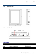
Quick Reference Guide 1.4 System Overview 1.4.1 Front & Top View 1.4.
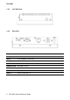
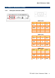
FPC-08R1 1.4.3 Left Side View 1.4.4 Rear View Connectors Label Function DC-IN +12V DC power-in connector Debug port Debug target application LAN RJ-45 Fast Ethernet connector MODE SWITCH Boot Mode selector Power S/W System power switch RESET Reset button USB1~2 USB 2.
Quick Reference Guide 2. Hardware Configuration Jumper and Connector Setting For advanced information, please refer to: 1- RSC-IMX51 Installation Guide or User’s Manual 2- AUX-MPCIE (Optional) Installation Guide. Note: If you need more information, please visit our website: http://www.avalue.com.
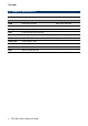
FPC-08R1 2.1 Jumper & connector list Connectors Label Function Note COM Serial port connector DB-9 male connector DC-IN +12V DC power-in connector Debug port Debug target application LAN RJ-45 Fast Ethernet connector MODE SWITCH Boot Mode selector OTG USB on The Go connector Power S/W System power switch RESET Reset button SD Card Slot SD/SDHC card socket USB USB 2.
Quick Reference Guide 2.2 Jumper & connector settings 2.2.
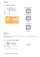
FPC-08R1 2.2.2 Boot Mode selector Boot from onboard SD Boot from SD socket Signal PIN PIN BMOD1 1 5 BMOD0 2 6 BT_SRC[1] 3 7 BT_SRC[0] 4 8 Signal +V2D775_BOOT +V1D8_DIG1 DIP ON ↓ USB OTG mode DIP ON ↓ Please note: DIP Switch setting: 0=Off, 1=On When Position4 is switched On, the system is forced to power On as soon as power is applied. Switch to Off mode for normal operation. 2.2.
Quick Reference Guide 2.2.
FPC-08R1 2.3 Installing SD Card (FPC-08R1) Step1. Put SD Card into the SD Card Slot.