ESM-QM87 Intel BGA Type CPU QM87 COM Express Type 6 Module User’s Manual 1st Ed – 20 January 2014 Copyright Notice Copyright 2014 Avalue Technology Inc., ALL RIGHTS RESERVED. Part No.
ESM-QM87 FCC Statement THIS DEVICE COMPLIES WITH PART 15 FCC RULES. OPERATION IS SUBJECT TO THE FOLLOWING TWO CONDITIONS: (1) THIS DEVICE MAY NOT CAUSE HARMFUL INTERFERENCE. (2) THIS DEVICE MUST ACCEPT ANY INTERFERENCE RECEIVED INCLUDING INTERFERENCE THAT MAY CAUSE UNDESIRED OPERATION. THIS EQUIPMENT HAS BEEN TESTED AND FOUND TO COMPLY WITH THE LIMITS FOR A CLASS "A" DIGITAL DEVICE, PURSUANT TO PART 15 OF THE FCC RULES.
Quick Installation Guide these products are free from patent, copyright, or mask work right infringement, unless otherwise specified. Applications that are described in this manual are for illustration purposes only. Avalue Technology Inc. makes no representation or warranty that such application will be suitable for the specified use without further testing or modification.
ESM-QM87 CONTENT 1. Getting Started ............................................................................................................ 7 1.1 Safety Precautions .................................................................................................... 7 1.2 Packing List ............................................................................................................... 7 1.3 Document Amendment History ............................................................................
Quick Installation Guide ESD/EMI solutions .................................................................................................. 33 2.5 3.BIOS Setup .................................................................................................................... 36 3.1 Introduction ............................................................................................................. 37 3.2 Starting Setup ...............................................................................
ESM-QM87 3.6.3.2.1 Graphics Configuration ........................................................................................................ 63 3.6.3.2.2 Memory Configuration......................................................................................................... 65 3.6.4 Boot .............................................................................................................................................. 66 3.6.4.1 CSM parameters.....................................
Quick Installation Guide 1. Getting Started 1.1 Safety Precautions Warning! Always completely disconnect the power cord from your chassis whenever you work with the hardware. Do not make connections while the power is on. Sensitive electronic components can be damaged by sudden power surges. Only experienced electronics personnel should open the PC chassis. Caution! Always ground yourself to remove any static charge before touching the CPU card.
ESM-QM87 1.
Quick Installation Guide 1.4 Manual Objectives This manual describes in details Avalue Technology ESM-QM87 Single Board. We have tried to include as much information as possible but we have not duplicated information that is provided in the standard IBM Technical References, unless it proved to be necessary to aid in the understanding of this board. We strongly recommend that you study this manual carefully before attempting to set up ESM-QM87 series or change the standard configurations.
ESM-QM87 1.5 System Specifications System CPU Intel Haswell Processor (25~ 47W CPU) BIOS AMI uEFI 128M-bit Flash ROM System Chipset Intel QM87 System Memory Two 204-pin DDR3L SODIMM socket, supports up to 16GB 1333/1600 SDRAM Expansion 7 PCIe x 1, 1 PCIe x 16 I/O MIO 4 x Serial ATA ports SMbus, LPC USB 8 x USB 2.0 , 4 x USB 3.
Quick Installation Guide 1.6 Architecture Overview—Block Diagram The following block diagram shows the architecture and main components of ESM-QM87.
ESM-QM87 2.
Quick Installation Guide 2.
ESM-QM87 14 ESM-QM87 Quick Installation Guide
Quick Installation Guide 2.2 Installation Procedure This chapter explains you the instructions of how to setup your system. 1. Turn off the power supply. 2. Insert the DIMM module (be careful with the orientation). 3. Insert all external cables for hard disk, keyboard, mouse, USB etc. except for flat panel. A CRT monitor must be connected in order to change NVRAM settings to support flat panel. 4. Connect power supply to the board via the ATXPWR. 5. Turn on the power. 6.
ESM-QM87 2.2.1 Main Memory ESM-QM87 provides two 204-pin SODIMM socket, supports up to 16GB DDR3L 1333/1600 SDRAM SODIMM Make sure to unplug the power supply before adding or removing DIMMs or other system components. Failure to do so may cause severe damage to board and components.
Quick Installation Guide Locate the SODIMM socket on the board. Carefully hold two edges of the SODIMM module. avoid touching its connectors. Align the notch key on the module with the rib on the slot. Firmly press the modules into the socket which automatically snaps into the mounting notch. Do not force the SODIMM module in with extra force as the SODIMM module only fits in one direction.
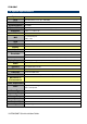
ESM-QM87 2.3 Connector List You can configure your board to match the needs of your application by setting jumpers. A jumper is the simplest kind of electric switch. It consists of two metal pins and a small metal clip (often protected by a plastic cover) that slides over the pins to connect them. To “close” a jumper you connect the pins with the clip. To “open” a jumper you remove the clip. Sometimes a jumper will have three pins, labeled 1, 2, and 3. In this case, you would connect either two pins.
Quick Installation Guide 2.4 Setting Jumpers & Connectors 2.4.1 AT/ATX mode selector (SW1) AT/ATX mode AT mode ATX mode* *Default 2.4.1.
ESM-QM87 2.4.
Quick Installation Guide Signal PIN PIN Signal GND A31 B31 GND HDA_BITCLK A32 B32 SPKR HDA_SDOUT A33 B33 NC BIOS_DIS0# A34 B34 NC NC A35 B35 NC USB6- A36 B36 USB7- USB6+ A37 B37 USB7+ USB_6_7_OC# A38 B38 USB_4_5_OC# USB4- A39 B39 USB5- USB4+ A40 B40 USB5+ GND A41 B41 GND USB2- A42 B42 USB3- USB2+ A43 B43 USB3+ USB_2_3_OC# A44 B44 USB_0_1_OC# USB0- A45 B45 USB1- USB0+ A46 B46 USB1+ VCC_RTC A47 B47 EXCD1_PERST# EXCD0_PERST# A48 B48 EXCD1_CPPE# EXCD0_CPPE
ESM-QM87 Signal PIN PIN Signal PCIE_TX2+ A61 B61 PCIE_RX2+ PCIE_TX2- A62 B62 PCIE_RX2- GPI1 A63 B63 GPO3 PCIE_TX1+ A64 B64 PCIE_RX1+ PCIE_TX1- A65 B65 PCIE_RX1- GND A66 B66 WAKE0# GPI2 A67 B67 WAKE1# PCIE_TX0+ A68 B68 PCIE_RX0+ PCIE_TX0- A69 B69 PCIE_RX0- GND A70 B70 GND LVDS_A0+ A71 B71 LVDS_B0+ LVDS_A0- A72 B72 LVDS_B0- LVDS_A1+ A73 B73 LVDS_B1+ LVDS_A1- A74 B74 LVDS_B1- LVDS_A2+ A75 B75 LVDS_B2+ LVDS_A2- A76 B76 LVDS_B2- LVDS_VDD_EN A77 B77 LVDS_B3+
Quick Installation Guide Signal PIN PIN Signal SPI_POWER A91 B91 VGA_GRN SPI_MISO A92 B92 VGA_BLU GPO0 A93 B93 VGA_HSYNC SPI_CLK A94 B94 VGA_VSYNC SPI_MOSI A95 B95 VGA_I2C_CK PP_TPM A96 B96 VGA_I2C_DAT TYPE10# A97 B97 SPI_CS# NC A98 B98 RSVD3 NC A99 B99 RSVD4 GND A100 B100 GND NC A101 B101 FAN_PWMOUT NC A102 B102 FAN_TACHIN LID# A103 B103 SLEEP# VCC A104 B104 VCC VCC A105 B105 VCC VCC A106 B106 VCC VCC A107 B107 VCC VCC A108 B108 VCC VCC A10
ESM-QM87 2.4.2.1 Signal Description – COM Express Connector 1 (CN1A) 2.4.2.1.1 Audio Signals Signal Signal Description HDA_SYNC HD Audio Sync HDA _RST# HD Audio Reset HDA _SDIN[0:2] Audio CODEC Serial Data HDA _BITCLK HD Audio Clock HDA _SDOUT HD Audio Data 2.4.2.1.2 Gigabit Ethernet Signals Signal Signal Description Gigabit Ethernet Controller 0: Media Dependent Interface Differential Pairs 0,1,2,3. The MDI can operate in 1000, 100 and 10 Mbit / sec modes.
Quick Installation Guide 2.4.2.1.4 Flat Panel LVDS Signals Signal Signal Description LVDS_BKLT_CTRL ENBKL# Controls panel digital power. Controls backlight power enable. 2.4.2.1.5 LPC Signals Signal Signal Description LPC_FRAME# LPC frame indicates the start of an LPC cycle LPC_AD[0:3] LPC multiplexed address, command and data bus LPC_DRQ[0:1]# LPC serial DMA request LPC_CLK LPC clock output - 33MHz nominal LPC_SERIRQ LPC serial interrupt 2.4.2.1.
ESM-QM87 2.4.2.1.8 Power Signals Signal Signal Description Standby power input: +5.0V nominal. See Electrical Specifications for allowable VCC_5V_SBY input range. If VCC5_SBY is used, all available VCC_5V_SBY pins on the connector(s) must be used. Only used for standby and suspend functions. May be left unconnected if these functions are not used in the system design. VCC_RTC Real-time clock circuit-power input. Nominally +3.0V. 2.4.2.1.
Quick Installation Guide 2.4.2.1.10 SATA Signals Signal Signal Description SATA[0:3]_TX +/- Serial ATA Channel 0-3 transmit differential pair. SATA[0:3]_RX +/- Serial ATA Channel 0-3receive differential pair. ATA_ACT# ATA (parallel and serial) activity indicator, active low. 2.4.2.1.11 VGA Signals Signal Signal Description VGA_RED Red for monitor. Analog DAC output. VGA_GRN Green for monitor. Analog DAC output. VGA_BLU Blue for monitor. Analog DAC output.
ESM-QM87 2.4.
Quick Installation Guide Signal PIN PIN Signal GND C31 D31 GND DDI2_CTRLCLK_AUX+ C32 D32 DDI1_PAIR2+ DDI2_CTRLDATA_AUX- C33 D33 DDI1_PAIR2- DDI2_DDC_AUX_SEL C34 D34 DDI1_DDC_AUX_SEL NC C35 D35 NC DDI3_CTRLCLK_AUX+ C36 D36 DDI1_PAIR3+ DDI3_CTRLDATA_AUX- C37 D37 DDI1_PAIR3- DDI3_DDC_AUX_SEL C38 D38 NC DDI3_PAIR0+ C39 D39 DDI2_PAIR0+ DDI3_PAIR0- C40 D40 DDI2_PAIR0- GND C41 D41 GND DDI3_PAIR1+ C42 D42 DDI2_PAIR1+ DDI3_PAIR1- C43 D43 DDI2_PAIR1- DDI3_HPD C44 D44 DDI2_HPD
ESM-QM87 Signal Signal PEG_RX3+ C61 D61 PEG_TX3+ PEG_RX3- C62 D62 PEG_TX3- NC C63 D63 NC NC C64 D64 NC- PEG_RX4+ C65 D65 PEG_TX4+ PEG_RX4- C66 D66 PEG_TX4- NC C67 D67 GND PEG_RX5+ C68 D68 PEG_TX5+ PEG_RX5- C69 D69 PEG_TX5- GND C70 D70 GND PEG_RX6+ C71 D71 PEG_TX6+ PEG_RX6- C72 D72 PEG_TX6- GND C73 D73 GND PEG_RX7+ C74 D74 PEG_TX7+ PEG_RX7- C75 D75 PEG_TX7- GND C76 D76 GND NC C77 D77 NC PEG_RX8+ C78 D78 PEG_TX8+ PEG_RX8- C79 D79 PEG_TX8- GND C80 D80 GND
Quick Installation Guide Signal PIN PIN Signal PEG_RX12+ C91 D91 PEG_TX12+ PEG_RX12- C92 D92 PEG_TX12- GND C93 D93 GND PEG_RX13+ C94 D94 PEG_TX13+ PEG_RX13- C95 D95 PEG_TX13- GND C96 D96 GND NC C97 D97 NC PEG_RX14+ C98 D98 PEG_TX14+ PEG_RX14- D99 PEG_TX14- GND C99 C100 D100 GND PEG_RX15+ C101 D101 PEG_TX15+ PEG_RX15- C102 D102 PEG_TX15- GND C103 D103 GND VCC C104 D104 VCC VCC C105 D105 VCC VCC C106 D106 VCC VCC C107 D107 VCC VCC C108 D108 VCC VC
ESM-QM87 2.4.3.1 Signal Description – COM Express Connector 2 (CN1B) 2.4.3.1.1 USB3.0 Signals Signal USB_SSTX[0:3]+ USB_SSTX[0:3]USB_SSRX[0:3]+ USB_SSRX[0:3]- Signal Description Additional transmit signal differential pairs for the SuperSpeed USB data path. Additional receive signal differential pairs for the SuperSpeed USB data path. 2.4.3.1.2 PEG Signals Signal PEG_TX[ 0:15]+ PEG_TX[ 0:15]PEG_RX[ 0:15]+ PEG_RX[ 0:15]PEG_LANE_RV# Signal Description PCI Express Graphics transmit differential paris.
Quick Installation Guide 2.5 ESD/EMI solutions Notification: There are some ESD/EMI solutions that users have to consider before designing your own Thermal solutions or Carrier board Thermal solution: Except CPU and Chipset contact area (Red Square), keep blue shade surface 5.45mm away from surface of ESM-QM87. Please refer to the pictures shown as below Heat Sink 5.
ESM-QM87 Make sure IO of your carrier board is grounding with chassis. You can implement conductive tape or EMI gasket.
Quick Installation Guide Make sure Hard disk is grounding with metal chassis. You can use conductive tape, metal bracket, or EMI gasket. Make sure trimming wires well; if it is not necessary please do not let your wire across the carrier board.
ESM-QM87 3.
Quick Installation Guide Introduction 3.1 Introduction The BIOS setup program allows users to modify the basic system configuration. In this following chapter will describe how to access the BIOS setup program and the configuration options that may be changed. 3.2 Starting Setup The AMI BIOS™ is immediately activated when you first power on the computer. The BIOS reads the system information contained in the NVRAM and begins the process of checking out the system and configuring it.
ESM-QM87 3.3 Using Setup In general, you use the arrow keys to highlight items, press to select, use the PageUp and PageDown keys to change entries, press for help and press to quit. The following table provides more detail about how to navigate in the Setup program using the keyboard.
Quick Installation Guide 3.4 Getting Help Press F1 to pop up a small help window that describes the appropriate keys to use and the possible selections for the highlighted item. To exit the Help Windows press or key. 3.5 In Case of Problems If, after making and saving system changes with Setup, you discover that your computer no longer is able to boot, the AMI BIOS supports an override to the NVRAM settings which resets your system to its defaults.
ESM-QM87 3.6 BIOS setup Once you enter the Setup Utility, the Main Menu will appear on the screen. The Main Menu allows you to select from several setup functions and exit choices. Use the arrow keys to select among the items and press to accept and enter the sub-menu. 3.6.1 Main Menu This section allows you to record some basic hardware configurations in your computer and set the system clock.
Quick Installation Guide 3.6.1.1 System Language This option allows choosing the system default language. 3.6.1.2 System Date Use the system date option to set the system date. Manually enter the day, month and year. 3.6.1.3 System Time Use the system time option to set the system time. Manually enter the hours, minutes and seconds. Note: The BIOS setup screens shown in this chapter are for reference purposes only, and may not exactly match what you see on your screen. Visit the Avalue website (www.
ESM-QM87 3.6.2 Advanced Menu This section allows you to configure your CPU and other system devices for basic operation through the following sub-menus. 3.6.2.1 APCI Settings Item Options APCI Sleep State Suspend Disabled S3 only(Suspend to RAM)[Default] S3 Video Repost ErP Function Disabled[Default] Enabled Disabled[Default] 42 ESM-QM87 Quick Installation Guide Description Select ACPI sleep state the system will enter when the SUSPEND button is pressed. Enable or Disable S3 Video Repost.
Quick Installation Guide Enabled Wakeup by Ring Watch Dog PWRON After PWR-Fail After G3 state Wakeup by Ring from S1~S5. On EV-EX14 carrier board, if you wanna enable LPC_PME function (such like the PS/2 Keyboard/Mouse wake from S1) please enable it. Disabled[Default] Enabled Disabled[Default] 30 sec 40 sec 50 sec 1 min 2 min 10 min 30 min Off[Default] On Former-Sts S5 State[Default] S0 State Select WatchDog. Select PWRON After PWR-Fail. System will return to S0 or S5 state after G3. 3.6.2.
ESM-QM87 3.6.2.2.1 Wake system with Fixed Time Item Wake up hour Wake up minute Wake up second Options 0-23 0-59 0-59 Description Select 0-23 For example enter 3 for 3am and 15 for 3pm. Select 0-59 For example enter 3 for 3am and 15 for 3pm. Select 0-59 For example enter 3 for 3am and 15 for 3pm. 3.6.2.3 Trusted Computing Item Options Security Device Support Disabled[Default], Enabled 44 ESM-QM87 Quick Installation Guide Description Enables or Disables BIOS support for security device. O.
Quick Installation Guide 3.6.2.4 CPU Configuration Use the CPU configuration menu to view detailed CPU specification and configure the CPU. Item Options Hyper-threading Disabled Enabled[Default] Active Processor Cores All[Default] Description Enabled for Windows XP and Linux (OS optimized for Hyper-Threading Technology) and Disabled for other OS (OS not optimized for Hyper-Threading Technology). When Disabled only one thread per enabled core is enabled.
ESM-QM87 1/2/3 Intel Virtualization Technology EIST CPU C states Enhanced C1 state CPU C3/6 Report C6 Latency CPU C7 Report C7 Latency Package C State limit Intel TXT(LT) Support Disabled Enabled[Default] Disabled Enabled[Default] Disabled Enabled[Default] Disabled Enabled[Default] Disabled Enabled[Default] Short[Default] Long Disabled CPU C7 CPU C7s[Default] Short Long[Default] C0/C1 C2 C3 C6 C7 C7s AUTO[Default] Disabled[Default] Enabled 46 ESM-QM87 Quick Installation Guide package When enabled, a
Quick Installation Guide 3.6.2.5 SATA Configuration It allows you to select the operation mode for SATA controller. Item SATA Controller(s) SATA Mode Selection SATA Controller Speed Options Enabled[Default] Disabled IDE AHCI[Default] RAID Default[Default] Gen1 Gen2 Gen3 Description Enable or disable SATA Device. Determines how SATA controller(s) operate. Indicates the maximum speed the SATA controller can support.
ESM-QM87 3.6.2.5.1 Software Feature Mask Configuration Item RAID0 RAID1 RAID10 Options Disabled Enabled[Default] Disabled Enabled[Default] Disabled Enabled[Default] 48 ESM-QM87 Quick Installation Guide Description Enable or disable RAID0 feature. Enable or disable RAID1 feature.
Quick Installation Guide 3.6.2.6 Intel® Rapid Start Technology Item Options Intel® Rapid Start Technology Enabled Disabled[Default] Description Enable or disable Intel® Rapid Start Technology. 3.6.2.7 PCH-FW Configuration Item MDES BIOS Status Code Options Disabled[Default] Enabled Description Enable/Disable MDES BIOS Status Code.
ESM-QM87 Firmware Update Configuration Configure Management Engine Technology Parameters. 3.6.2.7.1 Firmware Update Configuration Item Me FW Image Re-Flash Options Disabled[Default] Enabled Description Enable/Disable Me FW Image Re-Flash function. 3.6.2.8 AMT Configuration Intel AMT allows hardware-based remote management, security, power-management, and remote-configuration features.
Quick Installation Guide Item Options Intel AMT Enabled[Default] Disabled Un-Configure ME Disable ME Enabled Disabled[Default] Enabled Disabled[Default] Description Enable/Disable Intel ® Active Management Technology BIOS Extension. Note: iAMT H/W is always enabled. This option just controls the BIOS extension execution. If enabled, this requires additional firmware in the SPI device OEMFLag Bit 15: Un-Configure ME without password Set ME to Soft Temporary Disabled. 3.6.2.
ESM-QM87 3.6.2.10 H/W Monitor (IT8518) Item Smart Fan Function Smart Fan Mode Configuration Options Enabled Disabled[Default] Description Enable or Disable Smart Fan. Smart Fan Mode Select. 3.6.2.11 Super IO Configuration You can use this item to set up or change the Super IO configuration for serial ports.
Quick Installation Guide Item Serial Port 1 Configuration Serial Port 2 Configuration Parallel Port Configuration Watch Dog Options Enabled[Default] Disabled Enabled[Default] Disabled Enabled[Default] Disabled Disabled[Default] 30 Sec 40 Sec 50 Sec 60 Sec 2 Min 10 Min 30 Min Description Set Parameters of Serial Port 1 (COMA). Set Parameters of Serial Port 2 (COMB). Set Parameters of Parallel Port (LPT/LPTE). Set SIO watch dog timer. 3.6.2.11.
ESM-QM87 3.6.2.11.2 Serial Port 2 Configuration Item Option Enabled[Default] Disabled Serial Port Change Settings UART 232 422 485 Auto[Default] IO=2F8h; IRQ=3 IO=3F8h; IRQ=3,4,5,6,7,9,10,11,12 IO=2F8h; IRQ=3,4,5,6,7,9,10,11,12 IO=3E8h; IRQ=3,4,5,6,7,9,10,11,12 IO=2E8h; IRQ=3,4,5,6,7,9,10,11,12 UART 232[Default], UART 422, UART485 54 ESM-QM87 Quick Installation Guide Description Enable or Disable Serial Port (COM). Select an optimal setting for Super IO device.
Quick Installation Guide 3.6.2.11.3 Parallel Port Configuration Item Parallel Port Change Settings Device Mode Option Enabled[Default] Disabled Auto[Default] IO=378h; IRQ=5 IO=378h; IRQ=5,6,7,9,10,11,12 IO=278h; IRQ=5,6,7,9,10,11,12 Or Auto[Default] IO=378h; IRQ=5; DMA=3 IO=378h; IRQ=5,6,7,9,10,11,12; DMA=1,3; IO=278h; IRQ=5,6,7,9,10,11,12; DMA=1,3; STD Printer Mode[Default] SPP Mode EPP-1.9 and SPP Mode EPP-1.7 and SPP Mode ECP Mode ECP and EPP 1.9 Mode ECP and EPP 1.
ESM-QM87 3.6.2.12 Network Stack Item Network stack Ipv4 PXE Support Ipv6 PXE Support Options Enabled Disabled[Default] Enabled Disabled[Default] Enabled Disabled[Default] 56 ESM-QM87 Quick Installation Guide Description Enable/Disable UEFI network stack. Enable Ipv4 PXE Boot Support. If disabled IPV4 PXE boot option will not be created. Enable Ipv6 PXE Boot Support. If disabled IPV4 PXE boot option will not be created.
Quick Installation Guide 3.6.2.13 Intel RC Drivers Version Detail 3.6.2.
ESM-QM87 3.6.2.14.1 NIC Configuration Item Link Speed Wake On LAN Option Auto[Default] 10 Mbps Half 10 Mbps Full 100 Mbps Half 100 Mbps Full Disabled Enabled[Default] 58 ESM-QM87 Quick Installation Guide Description Specifies the port speed used for the selected boot protocol. Enables the server to be powered on using an in-band magic packet.
Quick Installation Guide 3.6.3 Chipset 3.6.3.1 PCH-IO Configuration Item PCI Express Configuration USB Configuration Option Description PCI Express Configuration settings. USB Configuration settings. PCH Azalia Configuration PCH Azalia Configuration settings. PCH LAN Controller Disabled Enabled[Default] Enable or disable onboard NIC.
ESM-QM87 SLP_S4 Assertion width Disabled 1-2 Seconds 2-3 Seconds 3-4 Seconds 4-5 Seconds[Default] 3.6.3.1.1 PCI Express Configuration 3.6.3.1.1.1 PCI Express Root Port 1/2/3/4/5/6/7 60 ESM-QM87 Quick Installation Guide Select a minimum assertion width of the SLP_S4# signal.
Quick Installation Guide Item PCI Express Root Port 1 ASPM Support PCIe Speed 3.6.3.1.2 Option Disabled Enabled[Default] Disabled L0s L1 L0sL1 Auto[Default] Auto[Default] Gen1 Gen2 Description Control the PCI Express Root Port. Set the ASPM Level: Force L0s – Force all links to L0s State : AUTO – BIOS auto configure : DISABLE – Disables ASPM. Select PCI Express port speed.
ESM-QM87 3.6.3.1.3 PCH Azalia Configuration 3.6.3.2 Item Option Azalia Disabled Enabled Auto[Default] System Agent (SA) Configuration 62 ESM-QM87 Quick Installation Guide Description Control Detection of the Azalia device. Disabled = Azalia will be unconditionally disabled. Enabled = Azalia will be unconditionally Enabled. Auto = Azalia will be enabled if present, disabled otherwise.
Quick Installation Guide Item Option Disabled Enabled[Default] VT-d 3.6.3.2.1 Description Check to enable VT-d function on MCH.
ESM-QM87 3.6.3.2.1 .1 LCD Control Item Primary IGFX Boot Display Add2 card HDMI/DP select Option VBIOS Default[Default] CRT Port-C HDMI LVDS Port-D DP Port-B (Add2 Card) HDMI[Default] DP Active LFP No LVDS eDP Port-A[Default] CH7511 EDID Panel Option 1024x768 24/1 800x600 18/1 1024x768 18/1[Default] 1366x768 18/1 1024x600 18/1 1280x800 18/1 1920x1200 24/2 640x480 18/1 800x400 18/1 64 ESM-QM87 Quick Installation Guide Description Select the Video Device which will be activated during POST.
Quick Installation Guide Backlight brightness LVDS Back Light PWM Frequency 3.6.3.2.2 1920x1080 18/2 1280x1024 24/2 1440x900 18/2 1600x1200 24/2 1366x768 24/1 1920x1080 24/2 1680x1050 24/2 00% 25% 50%[Default] 75% 100% 200 Hz[Default] 300 Hz 400 Hz 500 Hz 700 Hz 1 kHz 2 kHz 3 kHz 5 kHz 10 kHz 20 kHz Select LVDS back light PWM duty. Select LVDS back light PWM Frequency. Memory Configuration The information in this page may be different depends on user’s memory usage.
ESM-QM87 3.6.4 Boot Item Option Setup Prompt Timeout 1~ 65535 Bootup NumLock State Quiet Boot Fast Boot Boot Option Priorities CSM parameters On[Default] Off Disabled Enabled[Default] Disabled[Default] Enabled Description Number of seconds to wait for setup activation key. 65535(0xFFFF) means indefinite waiting. Select the Keyboard NumLock state Enables or disables Quiet Boot option Enables or disables boot with initialization of a minimal set of devices required to launch active boot option.
Quick Installation Guide 3.6.4.1 CSM parameters Item Launch CSM Boot Option filter Launch PXE OpROM policy Launch Storage OpROM policy Launch Video OpROM policy Other PCI device ROM priority Option Disabled Enabled[Default] UEFI and Legacy[Default] Legacy only UEFI only Do not launch[Default] UEFI only Legacy only Do not launch UEFI only Legacy only[Default] Do not launch UEFI only Legacy only[Default] UEFI OpROM[Default] Legacy OpROM Description This option controls if CSM will be launched.
ESM-QM87 3.6.
Quick Installation Guide 3.6.6 Save and exit 3.6.6.1 Save Changes and Reset Reset the system after saving the changes. 3.6.6.2 Discard Changes and Reset Any changes made to BIOS settings during this session of the BIOS setup program are discarded. The setup program then exits and reboots the controller. 3.6.6.3 Restore Defaults This option restores all BIOS settings to the factory default.
ESM-QM87 4. Drivers Installation Note: Installation procedures and screen shots in this section are for your reference and may not be exactly the same as shown on your screen.
Quick Installation Guide 4.1 Install Chipset Driver (For Intel QM87) Insert the Supporting DVD-ROM to DVD-ROM drive, and it should show the index page of Avalue’s products automatically. If not, locate Index.htm and choose the product from the menu left, or link to \Driver_Chipset\Intel\ESM-QM87. Note: The installation procedures and screen shots in this section are based on Windows 7 operation system. If the warning message appears while the installation process, click Continue to go on. Step 3.
ESM-QM87 Step 6. Click Finish to complete setup.
Quick Installation Guide 4.2 Install Display Driver (For Intel QM87) Insert the Supporting DVD-ROM to DVD-ROM drive, and it should show the index page of Avalue’s products automatically. If not, locate Index.htm and choose the product from the menu left, or link to \Driver_Video\ESM-QM87. Note: The installation procedures and screen shots in this section are based on Windows 7 operation system. Step 1. Click Next to continue installation. Step 2. Click Next. Step 3.
ESM-QM87 Step 6. Click Next. 74 ESM-QM87 Quick Installation Guide Step 7. Click Finish to complete setup.
Quick Installation Guide 4.3 Install LAN Driver (For Intel I217LM) Insert the Supporting DVD-ROM to DVD-ROM drive, and it should show the index page of Avalue’s products automatically. If not, locate Index.htm and choose the product from the menu left, or link to \Driver_Gigabit\Intel\I217LM\ESM-QM87_LAN. Note: The installation procedures and screen shots in this section are based on Windows 7 operation system. Step 3. Click Next. Step 1. Click Next to continue installation. Step 2. Click Next.
ESM-QM87 Step 6. Click Finish to complete setup.
Quick Installation Guide 4.4 Install USB 3.0 Driver Insert the Supporting DVD-ROM to DVD-ROM drive, and it should show the index page of Avalue’s products automatically. If not, locate Index.htm and choose the product from the menu left, or link to \Utility\ESM-QM87_USB3.0. Note: The installation procedures and screen shots in this section are based on Windows 7 operation system. If the warning message appears while the installation process, click Continue to go on. Step 3.
ESM-QM87 Step 6. Click Finish to complete setup.
Quick Installation Guide 4.5 Install ME Driver Insert the Supporting DVD-ROM to DVD-ROM drive, and it should show the index page of Avalue’s products automatically. If not, locate Index.htm and choose the product from the menu left, or link to \Utility\ESM-QM87_ME. Note: The installation procedures and screen shots in this section are based on Windows 7 operation system. If the warning message appears while the installation process, click Continue to go on. Step 3. Wait while installing. Step1.
ESM-QM87 5.
Quick Installation Guide Unit: mm ESM-QM87 Quick Installation Guide 81
ESM-QM87 82 ESM-QM87 Quick Installation Guide