ESM-QM77 Intel QM77 COM Express Type 6 Module User’s Manual 1st Ed – 29 January 2013 Notice This guide is designed for experienced users to perform quick setup of the system. For detailed information, please always refer to the electronic user's manual. Copyright Notice Copyright 2013 Avalue Technology Inc., ALL RIGHTS RESERVED. Part No.
ESM-QM77 FCC Statement THIS DEVICE COMPLIES WITH PART 15 FCC RULES. OPERATION IS SUBJECT TO THE FOLLOWING TWO CONDITIONS: (1) THIS DEVICE MAY NOT CAUSE HARMFUL INTERFERENCE. (2) THIS DEVICE MUST ACCEPT ANY INTERFERENCE RECEIVED INCLUDING INTERFERENCE THAT MAY CAUSE UNDESIRED OPERATION. THIS EQUIPMENT HAS BEEN TESTED AND FOUND TO COMPLY WITH THE LIMITS FOR A CLASS "A" DIGITAL DEVICE, PURSUANT TO PART 15 OF THE FCC RULES.
User’s Manual Your satisfaction is our primary concern. Here is a guide to Avalue’s customer services. To ensure you get the full benefit of our services, please follow the instructions below carefully. Technical Support We want you to get the maximum performance from your products. So if you run into technical difficulties, we are here to help. For the most frequently asked questions, you can easily find answers in your product documentation.
ESM-QM77 CONTENT 1. Getting Started ............................................................................................................ 7 1.1 Safety Precautions .................................................................................................... 7 1.2 Packing List ............................................................................................................... 7 1.3 Document Amendment History ............................................................................
User’s Manual Intel HD Graphics – 3 Active Displays Support ....................................................... 33 2.5 3.BIOS Setup .................................................................................................................... 34 3.1 Introduction ............................................................................................................. 35 3.2 Starting Setup .........................................................................................................
ESM-QM77 3.6.3.2.1 Memory Configuration ..................................................................................................... 66 3.6.3.2.2 GT – Power Management Configuration ........................................................................ 66 3.6.3.3 3.6.4 Graphics Configuration ........................................................................................................ 67 Boot .........................................................................................
User’s Manual 1. Getting Started 1.1 Safety Precautions Warning! Always completely disconnect the power cord from your chassis whenever you work with the hardware. Do not make connections while the power is on. Sensitive electronic components can be damaged by sudden power surges. Only experienced electronics personnel should open the PC chassis. Caution! Always ground yourself to remove any static charge before touching the CPU card. Modern electronic devices are very sensitive to static electric charges.
ESM-QM77 1.
User’s Manual 1.4 Manual Objectives This manual describes in details Avalue Technology ESM-QM77 Single Board. We have tried to include as much information as possible but we have not duplicated information that is provided in the standard IBM Technical References, unless it proved to be necessary to aid in the understanding of this board. We strongly recommend that you study this manual carefully before attempting to set up ESM-QM77 series or change the standard configurations.
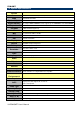
ESM-QM77 1.5 System Specifications System CPU Intel Core i7/i5/i3/Celeron (Socket-G2) Processors BIOS AMI 64M-bit SPI BIOS System Chipset Intel QM77 Chipset System Memory Two 204-pin DDR3 SODIMM socket, supports up to 16GB DDR3 1333/1600 SDRAM Expansion EEPROM 7 PCIe x1, 1 PCIe x16 ATMEL AT24C02 (Optional) I/O MIO 4 x Serial ATA, SMbus/ I2C Bus USB 8 x USB 2.0, 4 x USB3.0 DIO 4-bit GPI, 4-bit GPO Display Chipset Intel QM77 Chipset Integrated Memory DVMT 5.
User’s Manual 1.6 Architecture Overview—Block Diagram The following block diagram shows the architecture and main components of ESM-QM77.
ESM-QM77 2.
User’s Manual 2.
ESM-QM77 14 ESM-QM77 User’s Manual
User’s Manual 2.2 Installation Procedure This chapter explains you the instructions of how to setup your system. 1. Turn off the power supply. 2. Insert the DIMM module (be careful with the orientation). 3. Insert all external cables for hard disk, floppy, keyboard, mouse, USB etc. except for flat panel. A CRT monitor must be connected in order to change CMOS settings to support flat panel. 4. Connect power supply to the board via the ATXPWR. 5. Turn on the power. 6.
ESM-QM77 2.2.1 Main Memory ESM-QM77 provides two 204-pin DDR3 SODIMM socket, supports up to 16GB DDR3 1333/1600 SDRAM SODIMM Make sure to unplug the power supply before adding or removing DIMMs or other system components. Failure to do so may cause severe damage to board and components.
User’s Manual Locate the SODIMM socket on the board. Carefully hold two edges of the SODIMM module. avoid touching its connectors. Align the notch key on the module with the rib on the slot. Firmly press the modules into the socket which automatically snaps into the mounting notch. Do not force the SODIMM module in with extra force as the SODIMM module only fits in one direction.
ESM-QM77 2.3 Connector List You can configure your board to match the needs of your application by setting jumpers. A jumper is the simplest kind of electric switch. It consists of two metal pins and a small metal clip (often protected by a plastic cover) that slides over the pins to connect them. To “close” a jumper you connect the pins with the clip. To “open” a jumper you remove the clip. Sometimes a jumper will have three pins, labeled 1, 2, and 3. In this case, you would connect either two pins.
User’s Manual 2.4 Setting Jumpers & Connectors 2.4.1 AT/ATX mode selector (SW1) AT/ATX mode AT mode OFF 1 ON 2 ATX mode* OFF 1 ON 2 *Default 2.4.1.1 Signal Description –AT/ATX mode selection AT/ATX mode Description AT mode This Mode supports AT power supply, no need to press Power button to enable power on/off ATX mode This Mode supports ATX power supply.
ESM-QM77 2.4.
User’s Manual Signal PIN PIN Signal GND A31 B31 GND AC/HDA_BITCLK A32 B32 SPKR AC/HDA_SDOUT A33 B33 NC BIOS_DIS0# A34 B34 NC THRMTRIP# A35 B35 THRM# USB6- A36 B36 USB7- USB6+ A37 B37 USB7+ USB_6_7_OC# A38 B38 USB_4_5_OC# USB4- A39 B39 USB5- USB4+ A40 B40 USB5+ GND A41 B41 GND USB2- A42 B42 USB3- USB2+ A43 B43 USB3+ USB_2_3_OC# A44 B44 USB_0_1_OC# USB0- A45 B45 USB1- USB0+ A46 B46 USB1+ VCC_RTC A47 B47 EXCD1_PERST# EXCD0_PERST# A48 B48 EXCD1_CPPE# EXCD0_CP
ESM-QM77 Signal PIN PIN Signal PCIE_TX2+ A61 B61 PCIE_RX2+ PCIE_TX2- A62 B62 PCIE_RX2- GPI1 A63 B63 GPO3 PCIE_TX1+ A64 B64 PCIE_RX1+ PCIE_TX1- A65 B65 PCIE_RX1- GND A66 B66 WAKE0# GPI2 A67 B67 WAKE1# PCIE_TX0+ A68 B68 PCIE_RX0+ PCIE_TX0- A69 B69 PCIE_RX0- GND A70 B70 GND LVDS_A0+ A71 B71 LVDS_B0+ LVDS_A0- A72 B72 LVDS_B0- LVDS_A1+ A73 B73 LVDS_B1+ LVDS_A1- A74 B74 LVDS_B1- LVDS_A2+ A75 B75 LVDS_B2+ LVDS_A2- A76 B76 LVDS_B2- LVDS_VDD_EN A77 B77 LVDS_B3+ L
User’s Manual Signal PIN PIN Signal SPI_POWER A91 B91 VGA_GRN SPI_MISO A92 B92 VGA_BLU GPO0 A93 B93 VGA_HSYNC SPI_CLK A94 B94 VGA_VSYNC SPI_MOSI A95 B95 VGA_I2C_CK PP_TPM A96 B96 VGA_I2C_DAT TYPE10# A97 B97 SPI_CS# NC A98 B98 NC NC A99 B99 NC GND A100 B100 GND NC A101 B101 FAN_PWMOUT NC A102 B102 FAN_TACHIN LID# A103 B103 SLEEP# VCC_12V A104 B104 VCC_12V VCC_12V A105 B105 VCC_12V VCC_12V A106 B106 VCC_12V VCC_12V A107 B107 VCC_12V VCC_12V A108 B
ESM-QM77 2.4.2.1 Signal Description – COM Express Connector 1 (CN1A) 2.4.2.1.1 Audio Signals Signal Signal Description AC/HDA_SYNC HD Audio Sync AC/HDA _RST# HD Audio Reset AC/HDA _SDIN[0:2] Audio CODEC Serial Data AC/HDA _BITCLK HD Audio Clock AC/HDA _SDOUT HD Audio Data 2.4.2.1.2 Gigabit Ethernet Signals Signal Signal Description Gigabit Ethernet Controller 0: Media Dependent Interface Differential Pairs 0,1,2,3. The MDI can operate in 1000, 100 and 10 Mbit / sec modes.
User’s Manual 2.4.2.1.4 LPC Signals Signal Signal Description LPC_FRAME# LPC frame indicates the start of an LPC cycle LPC_AD[0:3] LPC multiplexed address, command and data bus LPC_DRQ[0:1]# LPC serial DMA request LPC_CLK LPC clock output - 33MHz nominal LPC_SERIRQ LPC serial interrupt 2.4.2.1.
ESM-QM77 2.4.2.1.7 Power Signals Signal Signal Description Standby power input: +5.0V nominal. See Electrical Specifications for allowable VCC_5V_SBY input range. If VCC5_SBY is used, all available VCC_5V_SBY pins on the connector(s) must be used. Only used for standby and suspend functions. May be left unconnected if these functions are not used in the system design. VCC_RTC Real-time clock circuit-power input. Nominally +3.0V. 2.4.2.1.
User’s Manual 2.4.2.1.10 VGA Signals Signal Signal Description VGA_RED Red for monitor. Analog DAC output. VGA_GRN Green for monitor. Analog DAC output. VGA_BLU Blue for monitor. Analog DAC output. VGA_HSYNC Horizontal sync output to VGA monitor VGA_VSYNC Vertical sync output to VGA monitor 2 DDC clock line (I2C port dedicated to identify VGA monitor capabilities) 2 DDC data line. VGA_ I C_CK VGA_ I C_DAT 2.4.2.1.
ESM-QM77 2.4.
User’s Manual Signal PIN PIN Signal GND C31 D31 GND DDI2_CTRLCLK_AUX+ C32 D32 DDI1_PAIR2+ DDI2_CTRLDATA_AUX- C33 D33 DDI1_PAIR2- DDI2_DDC_AUX_SEL C34 D34 DDI1_DDC_AUX_SEL NC C35 D35 NC DDI3_CTRLCLK_AUX+ C36 D36 DDI1_PAIR3+ DDI3_CTRLDATA_AUX- C37 D37 DDI1_PAIR3- DDI3_DDC_AUX_SEL C38 D38 NC DDI3_PAIR0+ C39 D39 DDI2_PAIR0+ DDI3_PAIR0- C40 D40 DDI2_PAIR0- GND C41 D41 GND DDI3_PAIR1+ C42 D42 DDI2_PAIR1+ DDI3_PAIR1- C43 D43 DDI2_PAIR1- DDI3_HPD C44 D44 DDI2_HPD NC C45 D45
ESM-QM77 Signal Signal PEG_RX3+ C61 D61 PEG_TX3+ PEG_RX3- C62 D62 PEG_TX3- NC C63 D63 NC NC C64 D64 NC- PEG_RX4+ C65 D65 PEG_TX4+ PEG_RX4- C66 D66 PEG_TX4- NC C67 D67 GND PEG_RX5+ C68 D68 PEG_TX5+ PEG_RX5- C69 D69 PEG_TX5- GND C70 D70 GND PEG_RX6+ C71 D71 PEG_TX6+ PEG_RX6- C72 D72 PEG_TX6- GND C73 D73 GND PEG_RX7+ C74 D74 PEG_TX7+ PEG_RX7- C75 D75 PEG_TX7- GND C76 D76 GND NC C77 D77 NC PEG_RX8+ C78 D78 PEG_TX8+ PEG_RX8- C79 D79 PEG_TX8- GND C80 D80 GND
User’s Manual Signal PIN PIN Signal PEG_RX12+ C91 D91 PEG_TX12+ PEG_RX12- C92 D92 PEG_TX12- GND C93 D93 GND PEG_RX13+ C94 D94 PEG_TX13+ PEG_RX13- C95 D95 PEG_TX13- GND C96 D96 GND NC C97 D97 NC PEG_RX14+ C98 D98 PEG_TX14+ PEG_RX14- D99 PEG_TX14- GND C99 C100 D100 GND PEG_RX15+ C101 D101 PEG_TX15+ PEG_RX15- C102 D102 PEG_TX15- GND C103 D103 GND VCC_12V C104 D104 VCC_12V VCC_12V C105 D105 VCC_12V VCC_12V C106 D106 VCC_12V VCC_12V C107 D107 VCC_12V VCC
ESM-QM77 2.4.3.1 Signal Description – COM Express Connector 2 (CN1B) 2.4.3.1.1 USB Signals Signal Signal Description USB_SSTX[0:3]+ Additional transmit signal differential pairs for the SuperSpeed USB data path. USB_SSTX[0:3]USB_SSRX[0:3]+ Additional receive signal differential pairs for the SuperSpeed USB data path. USB_SSRX[0:3]- 2.4.3.1.2 PEG Signals Signal Signal Description PEG_TX[ 0:15]+ PCI Express Graphics transmit differential paris.
User’s Manual 2.5 Intel HD Graphics – 3 Active Displays Support QM77 supports 3 Display Digital Ports B, C, D. (DDPB, DDPC and DDPD): DDPB: Capable of HDMI/DVI/DisplayPort/SDVO DDPC: Capable of HDMI/DVI/DisplayPort DDPD: Capable of HDMI/DVI/DisplayPort Due to the hardware design of ESM-QM77 and EEV-EX14, the onboard HDMI interface support by DDPC and Display Port is support by DDPD. DDPB is connected to Digital Display Interface(DDI), and it could support HDMI/DVI/DP/SDVO via add on adapter card.
ESM-QM77 3.
User’s Manual Introduction 3.1 Introduction The BIOS setup program allows users to modify the basic system configuration. In this following chapter will describe how to access the BIOS setup program and the configuration options that may be changed. 3.2 Starting Setup The AMI BIOS™ is immediately activated when you first power on the computer. The BIOS reads the system information contained in the CMOS and begins the process of checking out the system and configuring it.
ESM-QM77 3.3 Using Setup In general, you use the arrow keys to highlight items, press to select, use the PageUp and PageDown keys to change entries, press for help and press to quit. The following table provides more detail about how to navigate in the Setup program using the keyboard.
User’s Manual 3.4 Getting Help Press F1 to pop up a small help window that describes the appropriate keys to use and the possible selections for the highlighted item. To exit the Help Windows press or key. 3.5 In Case of Problems If, after making and saving system changes with Setup, you discover that your computer no longer is able to boot, the AMI BIOS supports an override to the CMOS settings which resets your system to its defaults.
ESM-QM77 3.6 BIOS setup Once you enter the AMI BIOS CMOS Setup Utility, the Main Menu will appear on the screen. The Main Menu allows you to select from several setup functions and exit choices. Use the arrow keys to select among the items and press to accept and enter the sub-menu. 3.6.1 Main Menu This section allows you to record some basic hardware configurations in your computer and set the system clock.
User’s Manual 3.6.1.1 System Language This option allows choosing the system default language. 3.6.1.2 System Date Use the system date option to set the system date. Manually enter the day, month and year. 3.6.1.3 System Time Use the system time option to set the system time. Manually enter the hours, minutes and seconds. Note: The BIOS setup screens shown in this chapter are for reference purposes only, and may not exactly match what you see on your screen. Visit the Avalue website (www.avalue.com.
ESM-QM77 3.6.2.1 APCI Settings Item APCI Sleep State S3 Video Repost 3.6.2.2 Options Suspend Disabled S1 only(CPU Stop Clock) S3 only(Suspend to RAM)[Default] Disabled[Default] Enabled S5 RTC Wake Settings 40 ESM-QM77 User’s Manual Description Select ACPI sleep state the system will enter when the SUSPEND button is pressed. Enable or Disable S3 Video Repost.
User’s Manual Item Options Wake system with Fixed Time Disabled[Default] Enabled Wake system with Dynamic Time Disabled[Default] Enabled 3.6.2.3 Description Enable or disable System wake on alarm event. When enabled, System will wake on the hr::min::sec specified. Enable or disable System wake on alarm event. When enabled, System will wake on the current time + Increase minute(s).
ESM-QM77 3.6.2.4 CPU Configuration Use the CPU configuration menu to view detailed CPU specification and configure the CPU.
User’s Manual 3.6.2.5 SATA Configuration It allows you to select the operation mode for SATA controller. Item SATA Controller(s) SATA Mode Selection SATA Test Mode Options Enabled[Default] Disabled IDE[Default] AHCI RAID Enabled Disabled[Default] Description Enable or disable SATA Device. Determines how SATA controller(s) operate. Enable or disable Test Mode.
ESM-QM77 3.6.2.6 Thermal Configuration Item Platform Thermal Configuration Description Platform Thermal Configuration options. 3.6.2.6.
User’s Manual Active Trip Point 0 Fan Speed 0-100[Default] Active Trip Point 1 Disabled 15C 23C 31C 39C 47C 55C[Default] 63C 71C 79C 87C 95C 103C 111C 119C Active Trip Point 1 Fan Speed 0-100 75[Default] Passive TC1 Value 1-16 1[Default] Passive TC2 Value 1-16 5[Default] Passive TSP Value 2-32 10[Default] PCH Thermal Device PCH Temp Read Disabled[Default] Enabled Disabled values recommended in BWG’s Thermal Reporting for Thermal Management settings. Set to Disabled for manual configuration.
ESM-QM77 CPU Energy Read CPU Temp Read Alert Enable Lock PCH Alert DIMM Alert 3.6.2.7 Enabled[Default] Disabled Enabled[Default] Disabled Enabled[Default] Disabled Enabled[Default] Disabled[Default] Enabled Disabled[Default] Enabled Intel® Rapid Start Technology 46 ESM-QM77 User’s Manual Enable. CPU Energy Read Enable. CPU Temperature Read Enable. Lock all Alert Enable settings. PCH Alert pin enable. DIMM Alert pin enable.
User’s Manual 3.6.2.8 Intel® TXT(LT) Configuration 3.6.2.9 PCH-FW Configuration Item MDES BIOS Status Code Firmware Update Configuration Options Disabled[Default] Enabled Description Enable/Disable MDES BIOS Status Code. Configure Management Engine Technology Parameters.
ESM-QM77 3.6.2.9.1 Firmware Update Configuration Item Me FW Image Re-Flash Options Disabled[Default] Enabled Description Enable/Disable Me FW Image Re-Flash function. 3.6.2.10 Intel® Anti- Theft Technology Configuration Item Intel® Anti- Theft Technology Intel® Anti- Theft Technology Rec 48 ESM-QM77 User’s Manual Options Disabled[Default] Enabled 1-64 3[Default] Description Enable/Disable Intel® AT in BIOS for testing only. Set the number of times Recovery attemped will be allowed.
User’s Manual 3.6.2.11 AMT Configuration Intel AMT allows hardware-based remote management, security, power-management, and remote-configuration features.
ESM-QM77 3.6.2.12 USB Configuration The USB Configuration menu helps read USB information and configures USB settings. Item Options Legacy USB Support Enabled[Default] Disabled Auto USB3.
User’s Manual 3.6.2.13 H/W Monitor2 Item Smart Fan Function Watchdog(7904) Options Description Enabled Enable or Disable Smart Fan. Disabled[Default] Disabled[Default]/1 Min/2 Min/3 Min /4 Min/5 Min/6 Min/7 Min/8Min/9 Min/10 Min 3.6.2.14 Super IO Configuration You can use this item to set up or change the Super IO configuration for serial ports. Please refer to 3.6.2.14.1, 3.6.2.14.2 and 3.6.2.14.3 for more information.
ESM-QM77 Item ERP Deep S5 Options Enabled Disabled[Default] Description Deep S5 for power saving. 3.6.2.14.1 Serial Port 1 Configuration Item Serial Port Change Settings 52 ESM-QM77 User’s Manual Option Enabled, Disabled[Default] Auto[Default] IO=3F8h; IRQ=4, IO=3F8h; IRQ=3,4,5,6,7,9,10,11,12 IO=2F8h; IRQ=3,4,5,6,7,9,10,11,12 IO=3E8h; IRQ=3,4,5,6,7,9,10,11,12 IO=2E8h; IRQ=3,4,5,6,7,9,10,11,12 Description Enable or Disable Serial Port (COM) Select an optimal setting for Super IO device.
User’s Manual 3.6.2.14.2 Serial Port 2 Configuration Item Option Enabled, Disabled[Default] Description Enable or Disable Serial Port (COM) Change Settings Auto[Default] IO=2F8h; IRQ=3 IO=3F8h; IRQ=3,4,5,6,7,9,10,11,12 IO=2F8h; IRQ=3,4,5,6,7,9,10,11,12 IO=3E8h; IRQ=3,4,5,6,7,9,10,11,12 IO=2E8h; IRQ=3,4,5,6,7,9,10,11,12 Select an optimal setting for Super IO device. UART 232 422 485 UART 232[Default] UART 422 UART 485 Serial Port Change the Serial Port as RS232/422/485.
ESM-QM77 3.6.2.14.3 Parallel Port Configuration Item Parallel Port Change Settings Device Mode 54 ESM-QM77 User’s Manual Option Enabled[Default] Disabled Auto[Default] IO=378h; IRQ=5 IO=378h; IRQ=5,6,7,9,10,11,12 IO=278h; IRQ=5,6,7,9,10,11,12 IO=3BCh; IRQ=5,6,7,9,10,11,12 STD Printer Mode[Default] SPP Mode EPP-1.9 and SPP Mode EPP-1.7 and SPP Mode ECP Mode ECP and EPP 1.9 Mode ECP and EPP 1.7 Mode Description Enable or Disable Parallel Port (LPT/LPTE). Select an optimal setting for super IO device.
User’s Manual 3.6.2.15 Intel® Smart Connect Technology Item ISCT Configuration Options Enabled Disabled[Default] Description Enable/Disable ISCT Configuration. 3.6.2.
ESM-QM77 Item EIST Turbo Mode CPU C3/6/7 Report Config TDP LOCK Long duration power limit Long duration maintained Short duration power limit ACPI T State 3.6.3 Chipset 56 ESM-QM77 User’s Manual Option Description Enable or Disable Intel SpeedStep. Disabled Turbo Mode. Enabled[Default] Enable or Disable CPU C3(ACPI C2)/C6(ACPI C3)/C7(ACPI C3) report to OS. Disabled[Default] Lock the Config TDP Control Enabled register. Long duration power limit in Watts, 0 means use factory default.
User’s Manual 3.6.3.1 PCH-IO Configuration Item PCI Express Configuration USB Configuration PCH Azalia Configuration Intel 82579 LAN (PHY) Wake on LAN High Precision Timer Restore AC Power Loss Option Description PCI Express Configuration settings. USB Configuration settings. PCH Azalia Configuration settings. Disabled Enable or disable onboard NIC. Enabled[Default] Disabled Enabled[Default] Enable or disable integrated LAN to wake the system.
ESM-QM77 3.6.3.1.1 PCI Express Configuration 3.6.3.1.1.
User’s Manual Item PCI Express Root Port 1/6/7 ASPM Support PCIe Speed Option Disabled Enabled[Default] Disabled L0s L1 L0sL1 Auto[Default] Auto[Default] Gen1 Gen2 Description Control the PCI Express Root Port. Set the ASPM Level: Force L0s – Force all links to L0s State : AUTO – BIOS auto configure : DISABLE – Disables ASPM. Select PCI Express port speed.
ESM-QM77 3.6.3.1.1.
User’s Manual Item PCI Express Root Port 2/3/4/5 ASPM Support URR FER NFER Option Disabled Enabled[Default] Disabled L0s L1 L0sL1 Auto[Default] Disabled[Default] Enabled Disabled[Default] Enabled Disabled[Default] Description Control the PCI Express Root Port. Set the ASPM Level: Force L0s – Force all links to L0s State : AUTO – BIOS auto configure : DISABLE – Disables ASPM. Enable or disable PCI Express Unsupported Request Reporting. Enable or disable PCI Express Device Fatal Error Reporting.
ESM-QM77 Enabled CER Disabled[Default] Enabled CTO Disabled[Default] Enabled SEFE Disabled[Default] Enabled SENFE Disabled[Default] Enabled SECE Disabled[Default] Enabled PME SCI Hot Plug PCIe Speed Disabled Enabled[Default] Disabled[Default] Enabled Auto[Default] Gen1 Gen2 Extra Bus Reserved 0 Reserved Memory 10 Prefetchable Memory 10 Reserved I/O 4K[Default]/8K/12K/16K/20K Device Non-Fatal Error Reporting. Enable or disable PCI Express Device Correctable Error Reporting.
User’s Manual 3.6.3.1.2 USB Configuration Item XHCI Pre-Boot Driver xHCI Mode HS Port #1/#2/#3/#4 Switchable xHCI Streams EHCI1/2 USB Ports Per-Port Disable Control Option Disabled Enabled[Default] Smart Auto[Default] Auto Enabled Disabled Disabled Enabled[Default] Disabled Enabled[Default] Disabled Enabled[Default] Disabled[Default] Enabled Description Enable or disable XHCI Pre-Boot Driver support. Mode of operation of xHCI controller. Allows for HS port switching between xHCI and EHCI.
ESM-QM77 3.6.3.1.3 PCH Azalia Configuration Item Option Azalia Disabled Enabled Auto[Default] Azalia Internal HDMI Codec Azalia HDMI codec Port B/C/D 64 ESM-QM77 User’s Manual Disabled Enabled[Default] Disabled Enabled[Default] Description Control Detection of the Azalia device. Disabled = Azalia will be unconditionally disabled. Enabled = Azalia will be unconditionally Enabled. Auto = Azalia will be enabled if present, disabled otherwise. Enable or disable internal HDMI codec for Azalia.
User’s Manual 3.6.3.2 System Agent (SA) Configuration Item VT-d CHAP Device ( B0:D7:F0) Thermal Device ( B0:D4:F0) Memory Configuration GT – Power Management Control Option Disabled Enabled[Default] Disabled[Default] Enabled Description Check to enable VT-d function on MCH. Enable or disable SA CHAP Device. Enable or disable SA Thermal Device. Memory Configuration Parameters. GT – Power Management Control Options.
ESM-QM77 3.6.3.2.1 Memory Configuration Item Memory Frequency Limiter 3.6.3.2.2 Option Auto[Default]/1067/1333/1600 /1867/2133/2400/2667 Description Maximum Memory Frequency Selections in Mhz. GT – Power Management Configuration Item GT OverClocking Support 66 ESM-QM77 User’s Manual Option Disabled[Default] Enabled Description Enable or disable GT OverClocking Support.
User’s Manual 3.6.3.3 Graphics Configuration Item Option Graphics Turbo IMON Current 14 ~31[Default] Primary Display Internal Graphics GTT Size Aperture Size Auto[Default] IGFX PEG PCI Auto[Default] Disabled Enabled 1MB 2MB[Default] 128MB 256MB [Default] 512MB Description Graphics turbo IMON current values supported (14 -31). Select which of IGFX/PEG/PCI Graphics device should be Primary Display Or select SG for Switchable Gfx. Keep IGD enabled based on the setup options.
ESM-QM77 LVDS Port-B (Add2 card) Port-C HDMI Port-D DP Secondary IGFX Boot Display Add2 Card HDMI/DP select LCD Panel Type Spread Spectrum clock Chip VBIOS Default CRT LVDS[Default] Port-B (Add2 card) Port-C HDMI Port-D DP HDMI[Default] DP VBIOS Default 640x480 18/1 800x600 18/1 1024x768 18/1[Default] 1280x1024 24/2 1024x600 18/1 800x600 18/1 1600x1200 24/2 1366x768 24/1 1680x1050 24/2 1920x1200 24/2 1440x900 24/2 1600x1200 24/2 1024x768 24/1 1280x800 18/1 1920x1080 24/2 2048x1536 24/2 Off[Default] Har
User’s Manual 3.6.4 Boot Item Option Setup Prompt Timeout 1~ 65535 Bootup NumLock State Quiet Boot On[Default] Off Disabled[Default] Enabled Fast Boot Disabled[Default] Enabled GateA20 Active Upon Request[Default] Always Option ROM Messages Force BIOS[Default] Keep Current Interrupt 19 Capture Disabled Enabled[Default] Boot Option Priorities Hard Drive BBS Priorities Description Number of seconds to wait for setup activation key. 65535(0xFFFF) means indefinite waiting.
ESM-QM77 3.6.4.1 CSM parameters Item Launch PXE OpROM policy Launch Storage OpROM policy Launch Video OpROM policy 70 ESM-QM77 User’s Manual Option Do not launch[Default] UEFI only Legacy only Do not launch UEFI only Legacy only[Default] Do not launch UEFI only Legacy only[Default] Description Controls the execution of UEFI and Legacy PXE OpROM. Controls the execution of UEFI and Legacy Storage OpROM. Controls the execution of UEFI and Legacy Video OpROM.
User’s Manual 3.6.
ESM-QM77 3.6.6 Save and exit 3.6.6.1 Save Changes and Exit Exit system setup after saving the changes. 3.6.6.2 Discard Changes and Exit Exit system setup without saving any changes.
User’s Manual 3.6.6.3 Save Changes and Reset Reset the system after saving the changes. 3.6.6.4 Discard Changes and Reset Any changes made to BIOS settings during this session of the BIOS setup program are discarded. The setup program then exits and reboots the controller. 3.6.6.5 Save Changes Save Changes done so far to any of the setup options. 3.6.6.6 Discard Changes Discard Changes done so far to any of the setup options. 3.6.6.
ESM-QM77 4. Drivers Installation Note: Installation procedures and screen shots in this section are for your reference and may not be exactly the same as shown on your screen.
User’s Manual 4.1 Install Chipset Driver (For Intel QM77) Insert the Supporting DVD-ROM to DVD-ROM drive, and it should show the index page of Avalue’s products automatically. If not, locate Index.htm and choose the product from the menu left, or link to \Driver_Chipset\Intel\ESM-QM77_INF. Note: The installation procedures and screen shots in this section are based on Windows 7 operation system. If the warning message appears while the installation process, click Continue to go on. Step 3. Click Next.
ESM-QM77 4.2 Install Display Driver (For Intel QM77) Insert the Supporting DVD-ROM to DVD-ROM drive, and it should show the index page of Avalue’s products automatically. If not, locate Index.htm and choose the product from the menu left, or link to \VGA\ESM-QM77_VGA. Note: The installation procedures and screen shots in this section are based on Windows 7 operation system. Step 3. Click Next. Step 4. Click Install. Step 1. Click Next to continue installation. Step 2.
User’s Manual Step 6. Click Finish to complete setup.
ESM-QM77 4.3 Install LAN Driver (For Intel 82579) Insert the Supporting DVD-ROM to DVD-ROM drive, and it should show the index page of Avalue’s products automatically. If not, locate Index.htm and choose the product from the menu left, or link to \Driver_Gigabit\Intel\82579\ESM-QM77_intel825 79. Note: The installation procedures and screen shots in this section are based on Windows 7 operation system. Step 2. Click Next. Step 3. Click Next to accept licence agreement. 78 ESM-QM77 User’s Manual Step 4.
User’s Manual Step 7. Click Finish to complete installation.
ESM-QM77 4.4 Install USB 3.0 Driver (For Intel QM77) Insert the Supporting DVD-ROM to DVD-ROM drive, and it should show the index page of Avalue’s products automatically. If not, locate Index.htm and choose the product from the menu left, or link to \Utility\ESM-QM77_USB 3.0. Note: The installation procedures and screen shots in this section are based on Windows 7 operation system. If the warning message appears while the installation process, click Continue to go on. Step1.
User’s Manual 4.5 Install ME Driver (For Intel QM77) Insert the Supporting DVD-ROM to DVD-ROM drive, and it should show the index page of Avalue’s products automatically. If not, locate Index.htm and choose the product from the menu left, or link to \Utility\ESM-QM77_ME_iAMP_vPRO. Note: The installation procedures and screen shots in this section are based on Windows 7 operation system. If the warning message appears while the installation process, click Continue to go on. Step1.
ESM-QM77 Step 6. Click Finish to complete setup.
User’s Manual 5.
ESM-QM77 Unit: mm 84 ESM-QM77 User’s Manual
User’s Manual ESM-QM77 User’s Manual 85