ERX-Q67 Intel® Q67 with Core™ i7/ i5 /i3 Micro-ATX Motherboard Quick Installation Guide 2nd Ed – 25 February 2014 Part No: E2017XQ6701R
ERX-Q67 FCC Statement THIS DEVICE COMPLIES WITH PART 15 FCC RULES. OPERATION IS SUBJECT TO THE FOLLOWING TWO CONDITIONS: (1) THIS DEVICE MAY NOT CAUSE HARMFUL INTERFERENCE. (2) THIS DEVICE MUST ACCEPT ANY INTERFERENCE RECEIVED INCLUDING INTERFERENCE THAT MAY CAUSE UNDESIRED OPERATION. THIS EQUIPMENT HAS BEEN TESTED AND FOUND TO COMPLY WITH THE LIMITS FOR A CLASS "A" DIGITAL DEVICE, PURSUANT TO PART 15 OF THE FCC RULES.
Quick Installation Guide Life Support Policy Avalue Technology’s PRODUCTS ARE NOT FOR USE AS CRITICAL COMPONENTS IN LIFE SUPPORT DEVICES OR SYSTEMS WITHOUT THE PRIOR WRITTEN APPROVAL OF Avalue Technology Inc. As used herein: 1.
ERX-Q67 and ready to give you the support you need to get the most from your Avalue’s products. In fact, most problems reported are minor and are able to be easily solved over the phone. In addition, free technical support is available from Avalue’s engineers every business day. We are always ready to give advice on application requirements or specific information on the installation and operation of any of our products. Please do not hesitate to call or e-mail us.
Quick Installation Guide 1. Getting Started 1.1 Safety Precautions Warning! Always completely disconnect the power cord from your chassis whenever you work with the hardware. Do not make connections while the power is on. Sensitive electronic components can be damaged by sudden power surges. Only experienced electronics personnel should open the PC chassis. Caution! Always ground yourself to remove any static charge before touching the CPU card.
ERX-Q67 2.
Quick Installation Guide 2.
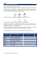
ERX-Q67 2.2 Jumper and Connector List You can configure your board to match the needs of your application by setting jumpers. A jumper is the simplest kind of electric switch. It consists of two metal pins and a small metal clip (often protected by a plastic cover) that slides over the pins to connect them. To “close” a jumper you connect the pins with the clip. To “open” a jumper you remove the clip. Sometimes a jumper will have three pins, labeled 1, 2, and 3.
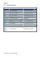
Quick Installation Guide Jumpers Label Function Note JCMOS1 Clear CMOS 3 x 1 header, pitch 2.54mm PSON1 AT/ATX Mode Select 3 x 1 header, pitch 2.54mm Rear Panel Connector Label Function Note KBMS PS/2 Keyboard and Mouse 6-pin Mini-Din COM1 COM1 Connector D-sub 9-pin, male DP1 DisplayPort Connector DisplayPort VGA1 VGA Port D-sub 15-pin, female HDMI1 HDMI Port HDMI 1.3 19-pin LAN1USB12 RJ-45 Ethernet Connector x 1 USB 2.
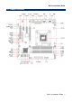
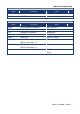
ERX-Q67 2.2.1 Internal Connectors Internal Connector Label Function Note FAN1 CPU Fan Connector 4 x 1 wafer, pitch 2.54mm FAN2 System Fan Connector 3 x 1 wafer, pitch 2.54mm FAN3 Chassis Fan Connector 3 x 1 wafer, pitch 2.54mm COM2 ~ 6 Serial Port Connector * 5 5 x 2 header, pitch 2.54mm JDIO1 Digital I/O Connector 6 x 2 header, pitch 2.54mm F_PANEL Front Panel connector 5 x 2 header, pitch 2.
Quick Installation Guide 2.
ERX-Q67 JDIO1 Digital I/O Connector F_PANEL Front Panel connector KBMS2 PS2 Keyboard & mouse connector FPAUD1 Audio Mic.-In & Line-Out Connector SPDIF_OUT SPDIF OUT TPM TPM Connector USB56 USB 2.