
User Manual
Quick Installation Guide
EPI-QM77 Quick Installation Guide 3
Content
1. Getting Started ........................................................................................................... 4
1.1 Safety Precautions ................................................................................................ 4
1.2 Packing List ........................................................................................................... 4
2. Hardware Configuration ............................................................................................ 5
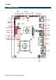
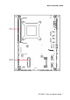
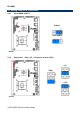
2.1 Product Overview .................................................................................................. 6
2.2 Jumper and Connector List.................................................................................... 8
2.3 Setting Jumpers & Connectors ............................................................................ 10
2.3.1 Clear CMOS (JBAT1) .............................................................................................................. 10
2.3.2 Serial port 1 - Ring, +5V, +12V power selector (JRI1) ............................................................ 10
2.3.3 AT/ATX mode selector, Front panel & LED settings (JFP1) ................................................... 11
2.3.4 Touch panel connector (JTOUCH_SEL1) ............................................................................... 11
2.3.5 Battery connector (BAT1) ........................................................................................................ 12
2.3.6 Audio connector (JAUDIO1) .................................................................................................... 12
2.3.6.1 Signal Description – Audio connector (JAUDIO1) ............................................. 12
2.3.7 CPU fan (CPU_FAN1) ............................................................................................................. 13
2.3.8 System fan connector (SYS_FAN1) ........................................................................................ 13
2.3.9 PS/2 keyboard & mouse connector (JKB/MS1) ...................................................................... 14
2.3.10 Serial port 1/ 2 connector (JCOM1/ JCOM2) .......................................................................... 14
2.3.11 Serial Port 1 connector (J422/1) .............................................................................................. 15
2.3.12 HD power connector (HD_PWR1) ........................................................................................... 15
2.3.13 LCD Inverter Connector 1 (JBKL1) ......................................................................................... 16
2.3.13.1 Signal Description – LCD Inverter Connector (JBKL1) ..................................... 16
2.3.14 LCD Backlight brightness adjustment (JVR1) ......................................................................... 16
2.3.15 5VSB connector in ATX (PWR_SB1) ...................................................................................... 17
2.3.16 IrDA connector (JIR1) .............................................................................................................. 17
2.3.17 LVDS connector (JLVDS1) ...................................................................................................... 18
2.3.18 Touch panel connector (JTOUCH1) ........................................................................................ 19
2.3.19 General purpose I/O connector (JDIO1) ................................................................................. 20
2.3.20 Power connector (PWR1) ........................................................................................................ 20
2.3.21 SPI connector (JSPI1) ............................................................................................................. 21
2.3.22 USB connector 4&5 (JUSB1_1) .............................................................................................. 21
2.4 Installing the CPU ................................................................................................ 22
2.4.1 Locate the CPU socket on the board. ...................................................................................... 22
2.4.2 Separate CPU cooler and its base first by screw drawer ........................................................ 23