EPI-QM67 Intel® Huron River QM67 EPIC Module with Intel® QM67 Chipset Quick Installation Guide 3rd Ed – 9 January 2013 Copyright Notice Copyright 2013 Avalue Technology Inc., ALL RIGHTS RESERVED. Part No.
EPI-QM67 FCC Statement THIS DEVICE COMPLIES WITH PART 15 FCC RULES. OPERATION IS SUBJECT TO THE FOLLOWING TWO CONDITIONS: (1) THIS DEVICE MAY NOT CAUSE HARMFUL INTERFERENCE. (2) THIS DEVICE MUST ACCEPT ANY INTERFERENCE RECEIVED INCLUDING INTERFERENCE THAT MAY CAUSE UNDESIRED OPERATION. THIS EQUIPMENT HAS BEEN TESTED AND FOUND TO COMPLY WITH THE LIMITS FOR A CLASS "A" DIGITAL DEVICE, PURSUANT TO PART 15 OF THE FCC RULES.
Quick Installation Guide Your satisfaction is our primary concern. Here is a guide to Avalue’s customer services. To ensure you get the full benefit of our services, please follow the instructions below carefully. Technical Support We want you to get the maximum performance from your products. So if you run into technical difficulties, we are here to help. For the most frequently asked questions, you can easily find answers in your product documentation.
EPI-QM67 Content 1. Getting Started ........................................................................................................... 5 1.1 Safety Precautions ................................................................................................ 5 1.2 Packing List ........................................................................................................... 5 2. Hardware Configuration ........................................................................................
Quick Installation Guide 1. Getting Started 1.1 Safety Precautions Warning! Always completely disconnect the power cord from your chassis whenever you work with the hardware. Do not make connections while the power is on. Sensitive electronic components can be damaged by sudden power surges. Only experienced electronics personnel should open the PC chassis. Caution! Always ground yourself to remove any static charge before touching the CPU card.
EPI-QM67 2.
Quick Installation Guide 2.
EPI-QM67 8 EPI-QM67 Quick Installation Guide
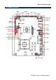
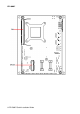
Quick Installation Guide 2.2 Jumper and Connector List You can configure your board to match the needs of your application by setting jumpers. A jumper is the simplest kind of electric switch. It consists of two metal pins and a small metal clip (often protected by a plastic cover) that slides over the pins to connect them. To “close” a jumper you connect the pins with the clip. To “open” a jumper you remove the clip. Sometimes a jumper will have three pins, labeled 1, 2, and 3.
EPI-QM67 Connectors Label Function Note BAT1 Battery connector 2 x 1 wafer, pitch 1.25mm CN1 Audio out connector Audio jack CN2 DVI connector CN4 204-pin DDR3 SODIMM CPU_FAN1 CPU Fan connector HDMI HDMI connector HD_PWR1 HD power connector 4 x 1 wafer, pitch 2.50mm J422/1 Serial port 2 in RS-422/485 mode 3 x 2 header, pitch 2.0mm JAUDIO1 Audio Connector 6 x 2 header, pitch 2.0mm JBKL1 LCD Inverter connector 1 5 x 1 wafer, pitch 2.
Quick Installation Guide 2.3 Setting Jumpers & Connectors 2.3.1 Clear CMOS (JBAT1) Protect* Clear CMOS *Default 2.3.
EPI-QM67 2.3.3 AT/ATX mode selector, Front panel & LED settings (JFP1) AT* ATX *Default Signal PIN PWBT 1, 2 RST# 3, 4 PWR-LED 5, 6 HDD-LED 7, 8 Short: AT MODE Open: ATX MODE COPEN# 2.3.
Quick Installation Guide 2.3.5 Battery connector (BAT1) 2.3.6 Signal PIN GND 2 VBAT 1 Audio connector (JAUDIO1) Signal PIN PIN Signal GND 12 11 MIC1_JD LINE1_JD 10 9 FRONT_JD MIC_LIN 8 7 MIC_RIN LINE_LIN 6 5 LINE_RIN GND 4 3 GND LOUT 2 1 ROUT 2.3.6.
EPI-QM67 2.3.7 CPU fan / System fan connector (CPU_FAN1/ SYS_FAN1) CPU_FAN SYS_FAN1 SYS_FAN CPU_FAN1 2.3.
Quick Installation Guide 2.3.9 Serial port 1/ 2 connector (JCOM1/ JCOM2) JCOM1/JCOM2 2.3.10 Signal PIN IN Signal NC 20 19 RI2 CTS2 18 17 RST2 DSR2 16 15 GND DTR2 14 13 TXD2 RXD2 12 11 DCD2 NC 10 9 RI1 CTS1 8 7 RST1 DSR1 6 5 GND DTR1 4 3 TXD1 RXD1 2 1 DCD1 Serial port 1/2 in RS-422/485 mode connector (J422/1) Signal PIN PIN Signal GND 6 5 +5V RX+ 4 3 TX+ RX- 2 1 TX- Note: J422/1 is available after modifying the mode of COM2 in BIOS setting.
EPI-QM67 2.3.11 2.3.12 HD power connector (HD_PWR1) Signal PIN +5V 4 +5V 3 GND 2 GND 1 LCD Inverter Connector 1 (JBKL1) JBKL1 Signal PIN +5V 5 BRIGHT 4 BLK_ON 3 GND 2 +12V 1 2.3.12.1 Signal Description – LCD Inverter Connector (JBKL1) Signal Signal Description BRIGHT Vadj = 0.75V ~ 4.25V (Recommended: 4.
Quick Installation Guide 2.3.13 2.3.
EPI-QM67 2.3.15 2.3.
Quick Installation Guide 2.3.
EPI-QM67 2.3.18 General purpose I/O connector (JDIO1) Signal 2.3.
Quick Installation Guide 2.3.20 SPI connector (JSPI1) Signal 2.3.21 PIN PIN Signal 7 HOLD# SPI_SI 6 5 SPI_SO SPI_CLK 4 3 SPI_CS#0 GND 2 1 +3.3V USB connector 4&5/ 6&7/ 8&9 (JUSB1_1/ JUSB1_2/ JUSB1_3) JUSB1_3 JUSB1_2 JUSB1_1 Signal PIN PIN Signal +5V 1 2 GND USB_DN4/6/8 3 4 GND USB_DP4/6/8 5 6 USB_DP5/7/9 GND 7 8 USB_DN5/7/9 GND 9 10 +5V Note: Wrong USB cable configuration with USB devices might damage USB devices.
EPI-QM67 2.4 Installing the CPU 2.4.1 Locate the CPU socket on the board. Before installing the CPU, make sure that the socket box is facing towards you and the load lever is on your left.
Quick Installation Guide 2.4.2 Separate CPU cooler and its base first by screw drawer 1.
EPI-QM67 2. turn the CPU lock clockwise to lock CPU The CPU fits in only one correct orientation.