
User Manual

User’s Manual
EPI-LX800 Series User’s Manual
37
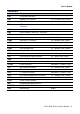
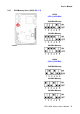
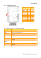
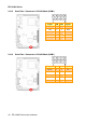
2.4.10 Parallel Port Connector (CN2)
Signal PIN PIN Signal
STB# 1 2 AFD#
PD0 3 4 ERR#
PD1 5 6 INIT
PD2 7 8 SLIN#
PD3 9 10 GND
PD4 11 12 GND
PD5 13 14 GND
PD6 15 16 GND
PD7 17 18 GND
ACK# 19 20 GND
BUSY 21 22 GND
PE 23 24 GND
SLCT 25 26 NC
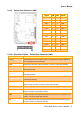
2.4.10.1 Signal Description – Parallel Port Connector (CN2)
Signal Signal Description
PD [7:0] Parallel data bus from PC board to printer. The data lines are able to operate in
PS/2 compatible bi-directional mode.
SLIN# Output line for detection of printer selection. This pin is pulled high internally.
SLCT An active high input on this pin indicates that the printer is selected. This pin is
pulled high internally.
STB# An active low output is used to latch the parallel data into the printer. This pin is
pulled high internally.
BUSY An active high input indicates that the printer is not ready to receive data. This pin
is pulled high internally.
ACK# An active low input on this pin indicates that the printer has received data and is
ready to accept more data. This pin is pulled high internally.
INIT# Output line for the printer initialization. This pin is pulled high internally.
AFD# An active low output from this pin causes the printer to auto feed a line after a line
is printed. This pin is pulled high internally.
ERR# An active low input on this pin indicates that the printer has encountered an error
condition. This pin is pulled high internally.
PE# An active high input on this pin indicates that the printer has detected the end of
the paper. This pin is pulled high internally.