EMX-NM70 Intel® Celeron® Processor Mini ITX Motherboard with Intel® NM70 Express Chipset Quick Installation Guide 1st Ed – 26 June 2013 Part No.
EMX-NM70 Quick Installation Guide FCC Statement THIS DEVICE COMPLIES WITH PART 15 FCC RULES. OPERATION IS SUBJECT TO THE FOLLOWING TWO CONDITIONS: (1) THIS DEVICE MAY NOT CAUSE HARMFUL INTERFERENCE. (2) THIS DEVICE MUST ACCEPT ANY INTERFERENCE RECEIVED INCLUDING INTERFERENCE THAT MAY CAUSE UNDESIRED OPERATION. THIS EQUIPMENT HAS BEEN TESTED AND FOUND TO COMPLY WITH THE LIMITS FOR A CLASS "A" DIGITAL DEVICE, PURSUANT TO PART 15 OF THE FCC RULES.
EMX-NM70 Quick Installation Guide Content 1. Getting Started ............................................................................................................ 4 1.1 Safety Precautions .......................................................................................... 4 1.2 Packing List .................................................................................................... 4 2. Hardware Configuration ..........................................................................
EMX-NM70 Quick Installation Guide 1. Getting Started 1.1 Safety Precautions Warning! Always completely disconnect the power cord from your chassis whenever you work with the hardware. Do not make connections while the power is on. Sensitive electronic components can be damaged by sudden power surges. Only experienced electronics personnel should open the PC chassis. Caution! Always ground yourself to remove any static charge before touching the CPU card.
EMX-NM70 Quick Installation Guide 2.
EMX-NM70 Quick Installation Guide 2.
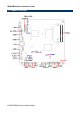
EMX-NM70 Quick Installation Guide 2.2 Jumper and Connector List You can configure your board to match the needs of your application by setting jumpers. A jumper is the simplest kind of electric switch. It consists of two metal pins and a small metal clip (often protected by a plastic cover) that slides over the pins to connect them. To “close” a jumper you connect the pins with the clip. To “open” a jumper you remove the clip. Sometimes a jumper will have three pins, labeled 1, 2, and 3.
EMX-NM70 Quick Installation Guide CIR CIR connector 1 x 3 header, pitch 2.00 mm FPANEL Front Panel Switches 2 x 5 header, pitch 2.54 mm JLVDS1 LVDS connector 2 x 20 wafer, pitch 1.00 mm JSPK Speaker Headers 1 x 4 wafer, pitch 2.00 mm HDMI HDMI connector INCN1 LCD Inverter connector 5 x 1 header, pitch 2.54 mm SATA1/2 Serial ATA connector 1/2 SATA 7P connector VSATA1/2 SATA Power connector 1/2 1 x 4 wafer, pitch 2.50 mm JCOM1/2 Serial port 1/2 connector 2 x 5 header, pitch 2.
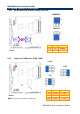
EMX-NM70 Quick Installation Guide 2.3 Setting Jumpers & Connectors 2.3.1 mSATA/Mini PCIe function Jumper (JS1/JS2) MINIPCIE* M-SATA JS2 JS1 * Default 2.3.2 Pin Pin Signal 1-3 2-4 M-SATA 3-5 4-6 MINIPCIE Jumper for LVDS power (PWR_LVDS) +3.3V* +12V +5V PIN Signal Max current 1-2 +3.3V 1A * Default 3-4 +5V 1A Note: This jumper is working for LVDS power.
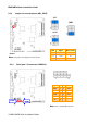
EMX-NM70 Quick Installation Guide 2.3.3 Jumper for inverter power (ADJ_PWR) +5V* GND +3.3V PIN Signal Max current 1-2 +5V 1A 3-4 +3.3V 1A 5-6 GND * Default Note: This jumper is working for inverter power. 2.3.4 Serial port 1/2 connector (JCOM1/2) Signal JCOM2 PIN PIN Signal DCD 1 2 RXD TXD 3 4 DTR GND 5 6 DSR RTS 7 8 CTS RI 9 JCOM1 Note: Com 1/2 Pin9 without power.
EMX-NM70 Quick Installation Guide 2.3.5 Front Panel Switches (FPANEL) Signal 2.3.
EMX-NM70 Quick Installation Guide 2.3.7 LVDS connector (JLVDS1) Signal Note: Mapping connector DF13-40DS-1.25C (1.0mm).
EMX-NM70 Quick Installation Guide 2.3.8 General Purpose I/O (GPIO1) Signal 2.3.9 PIN PIN Signal +3.3V 1 2 GND GPIO0 3 4 GPIO68 GPIO1 5 6 GPIO69 GPIO6 7 8 GPIO70 GPIO16 9 10 GPIO71 USB Connector 1 - USB2.
EMX-NM70 Quick Installation Guide 2.3.10 2.3.11 CIR connector (CIR) PIN Signal 1 5VSB 2 GND 3 RX/TX PIN Signal 1 INTSPL+ 2 INTSPL- 3 INTSPR+ 4 INTSPR- Speaker Headers (JSPK) Note: Support 3W 4ΩX 2 speaker. Mapping connector PHR-4.
EMX-NM70 Quick Installation Guide 2.3.12 Power connector (J1) Signal PIN PIN Signal GND 2 4 +19V GND 1 3 +19V Note: Power input +19V only.
EMX-NM70 Quick Installation Guide 2.3.