EMX-NM70 Intel® Celeron® Processor Mini ITX Motherboard with Intel® NM70 Express Chipset User’s Manual 1st Ed – 18 July 2013 Part No.
EMX-NM70 User’s Manual FCC Statement THIS DEVICE COMPLIES WITH PART 15 FCC RULES. OPERATION IS SUBJECT TO THE FOLLOWING TWO CONDITIONS: (1) THIS DEVICE MAY NOT CAUSE HARMFUL INTERFERENCE. (2) THIS DEVICE MUST ACCEPT ANY INTERFERENCE RECEIVED INCLUDING INTERFERENCE THAT MAY CAUSE UNDESIRED OPERATION. THIS EQUIPMENT HAS BEEN TESTED AND FOUND TO COMPLY WITH THE LIMITS FOR A CLASS "A" DIGITAL DEVICE, PURSUANT TO PART 15 OF THE FCC RULES.
EMX-NM70 User’s Manual Content 1. Getting Started ............................................................................................................ 5 1.1 Safety Precautions .......................................................................................... 5 1.2 Packing List .................................................................................................... 5 1.3 Document Amendment History ....................................................................... 6 1.
EMX-NM70 User’s Manual 3.6.1.3 System Time .................................................................................. 29 3.6.2 Advanced BIOS settings ....................................................................... 30 3.6.2.1 CPU Configuration ......................................................................... 30 3.6.2.2 Onboard Device Configuration ....................................................... 31 3.6.2.3 USB Legacy Features ....................................................
EMX-NM70 User’s Manual 1. Getting Started 1.1 Safety Precautions Warning! Always completely disconnect the power cord from your chassis whenever you work with the hardware. Do not make connections while the power is on. Sensitive electronic components can be damaged by sudden power surges. Only experienced electronics personnel should open the PC chassis. Caution! Always ground yourself to remove any static charge before touching the CPU card.
EMX-NM70 User’s Manual 1.
EMX-NM70 User’s Manual 1.4 Manual Objectives This manual describes in details Avalue Technology EMX-NM70 Single Board. We have tried to include as much information as possible but we have not duplicated information that is provided in the standard IBM Technical References, unless it proved to be necessary to aid in the understanding of this board. We strongly recommend that you study this manual carefully before attempting to set up EMX-NM70 series or change the standard configurations.
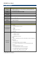
EMX-NM70 User’s Manual 1.5 Specifications System CPU Intel® Celeron® Processor 1037U (2M Cache,1.80 GHz) upgradable with Celeron level Processor BIOS AMI uEFI BIOS, 64Mbit SPI Flash ROM System Chipset Intel® NM70 Express Chipset I/O Chip nuvoTon NCT6106D System Memory 1 x 204-pin DDR3 1333 SODIMMs, up to 8GB H/W Reset, 1sec. – 65535sec./min. 1sec. or 1min.
EMX-NM70 User’s Manual 1 x 4 pin , pitch 2.54mm connector for speaker 1 x 3 pin , pitch 2.
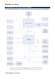
EMX-NM70 User’s Manual 1.6 Architecture Overview—Block Diagram The following block diagram shows the architecture and main components of EMX-NM70.
EMX-NM70 User’s Manual The following block diagram shows the architecture and main components of EMX-NM70-GPU.
EMX-NM70 User’s Manual 2.
EMX-NM70 User’s Manual 2.
EMX-NM70 User’s Manual 2.2 Installation Procedure This chapter explains you the instructions of how to setup your system. 1. Turn off the power supply. 2. Insert the DIMM module (be careful with the orientation). 3. Insert all external cables for hard disk, floppy, keyboard, mouse, USB etc. except for flat panel. A CRT monitor must be connected in order to change BIOS settings to support flat panel. 4. Connect power supply to the board via the AC/DC Adapter. 5. Turn on the power. 6.
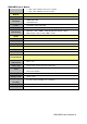
EMX-NM70 User’s Manual 2.3 Jumper and Connector List You can configure your board to match the needs of your application by setting jumpers. A jumper is the simplest kind of electric switch. It consists of two metal pins and a small metal clip (often protected by a plastic cover) that slides over the pins to connect them. To “close” a jumper you connect the pins with the clip. To “open” a jumper you remove the clip. Sometimes a jumper will have three pins, labeled 1, 2, and 3.
EMX-NM70 User’s Manual CIR CIR connector 1 x 3 header, pitch 2.00 mm FPANEL Front Panel Switches 2 x 5 header, pitch 2.54 mm JLVDS1 LVDS connector 2 x 20 wafer, pitch 1.00 mm JSPK Speaker Headers 1 x 4 wafer, pitch 2.00 mm HDMI HDMI connector INCN1 LCD Inverter connector 5 x 1 header, pitch 2.54 mm SATA1/2 Serial ATA connector 1/2 SATA 7P connector VSATA1/2 SATA Power connector 1/2 1 x 4 wafer, pitch 2.50 mm JCOM1/2 Serial port 1/2 connector 2 x 5 header, pitch 2.
EMX-NM70 User’s Manual 2.4 Setting Jumpers & Connectors 2.4.1 mSATA/Mini PCIe function Jumper (JS1/JS2) MINIPCIE* M-SATA JS2 JS1 * Default 2.4.2 Pin Pin Signal 1-3 2-4 M-SATA 3-5 4-6 MINIPCIE Jumper for LVDS power (PWR_LVDS) +3.3V* +12V +5V PIN Signal Max current 1-2 +3.3V 1A * Default 3-4 +5V 1A Note: This jumper is working for LVDS power.
EMX-NM70 User’s Manual 2.4.3 Jumper for inverter power (ADJ_PWR) +5V* GND +3.3V PIN Signal Max current 1-2 +5V 1A 3-4 +3.3V 1A 5-6 GND * Default Note: This jumper is working for inverter power. 2.4.4 Serial port 1/2 connector (JCOM1/2) Signal JCOM2 PIN PIN Signal DCD 1 2 RXD TXD 3 4 DTR GND 5 6 DSR RTS 7 8 CTS RI 9 JCOM1 Note: Com 1/2 Pin9 without power.
EMX-NM70 User’s Manual 2.4.5 Front Panel Switches (FPANEL) Signal 2.4.
EMX-NM70 User’s Manual 2.4.7 LVDS connector (JLVDS1) Signal Note: Mapping connector DF13-40DS-1.25C (1.0mm).
EMX-NM70 User’s Manual 2.4.8 General Purpose I/O (GPIO1) Signal 2.4.9 PIN PIN Signal +3.3V 1 2 GND GPIO0 3 4 GPIO68 GPIO1 5 6 GPIO69 GPIO6 7 8 GPIO70 GPIO16 9 10 GPIO71 USB Connector 1 - USB2.
EMX-NM70 User’s Manual 2.4.10 2.4.11 CIR connector (CIR) PIN Signal 1 5VSB 2 GND 3 RX/TX PIN Signal 1 INTSPL+ 2 INTSPL- 3 INTSPR+ 4 INTSPR- Speaker Headers (JSPK) Note: Support 3W 4ΩX 2 speaker. Mapping connector PHR-4.
EMX-NM70 User’s Manual 2.4.12 Power connector (J1) Signal PIN PIN Signal GND 2 4 +19V GND 1 3 +19V Note: Power input +19V only.
EMX-NM70 User’s Manual 2.4.
EMX-NM70 User’s Manual 3.
EMX-NM70 User’s Manual 3.1 Introduction The BIOS setup program allows users to modify the basic system configuration. In this following chapter will describe how to access the BIOS setup program and the configuration options that may be changed. 3.2 Starting Setup The BIOS is immediately activated when you first power on the computer. The BIOS reads the system information contained in the NVRAM and begins the process of checking out the system and configuring it.
EMX-NM70 User’s Manual 3.3 Using Setup In general, you use the arrow keys to highlight items, press to select, use the PageUp and PageDown keys to change entries, press for help and press to quit. The following table provides more detail about how to navigate in the Setup program using the keyboard.
EMX-NM70 User’s Manual 3.4 Getting Help Press F1 to pop up a small help window that describes the appropriate keys to use and the possible selections for the highlighted item. To exit the Help Window press or the F1 key again. 3.5 In Case of Problems If, after making and saving system changes with Setup, you discover that your computer no longer is able to boot, the BIOS supports an override to the NVRAM settings which resets your system to its defaults.
EMX-NM70 User’s Manual 3.6 BIOS setup Once you enter the BIOS Setup Utility, the Main Menu will appear on the screen. The Main Menu allows you to select from several setup functions and exit choices. Use the arrow keys to select among the items and press to accept and enter the sub-menu. 3.6.1 Main Menu This section allows you to record some basic hardware configurations in your computer and set the system clock. 3.6.1.1 System Language Use this option to select system language 3.6.1.
EMX-NM70 User’s Manual 3.6.2 Advanced BIOS settings This section allows you to configure your CPU and other system devices for basic operation through the following sub-menus. 3.6.2.1 CPU Configuration Use the CPU configuration menu to view detailed CPU specification and configure the CPU.
EMX-NM70 User’s Manual 3.6.2.2 Onboard Device Configuration Item Onboard Lan Control Lan Pxe OpROM Control Storage OpROM Control Onboard Audio Control Internal HDMI Audio Control Mini Pcie Control (Port4) USB Control Options Disabled Enabled[Default] Disabled[Default] Enabled Disabled Enabled[Default] Disabled Enabled[Default] Disabled[Default] Enabled Disabled Enabled[Default] Disabled Enabled[Default] Description Enable or disable Onboard NIC. Controls the execution of PXE OpROM.
EMX-NM70 User’s Manual 3.6.2.3 USB Legacy Features Item Options Legacy USB Support Enabled[Default] Disabled Auto XHCI Hand-off Disabled Enabled[Default] EHCI Hand-off Disabled[Default] Enabled Port 60/64 Emulation Disabled Enabled[Default] 32 EMX-NM70 User’s Manual Description Enables Legacy USB support, AUTO option disables legacy support if no USB devices are connected. DISABLE option will keep USB devices available only for EFI applications.
EMX-NM70 User’s Manual 3.6.2.4 Inter® Rapid Start Technology 3.6.2.
EMX-NM70 User’s Manual Wake By PME S1 only(CPU Stop Clock) S3 only(Suspend to RAM) [Default] Auto Disabled Enabled[Default] USB Keyboard/Mouse when the SUSPEND button is pressed. Wakeup By PME. Disabled Enabled[Default] Enabled/Disabled Wakeup From S3/S4 By USB KB/MS. Power-Loss State Always off[Default] Always on Keep last state Control the status when Power loss occurs. Poweron By RTC Disabled[Default] Enabled S3/S4 Wake Enable or disable System wake on alarm event.
EMX-NM70 User’s Manual 3.6.2.6.1 Serial Port 1 Configuration Item Serial Port Change Settings 3.6.2.6.2 Option Disabled Enabled[Default] Auto[Default] IO=3F8h; IRQ=4; IO=3F8h; IRQ=3,4,5,6,7,,10,11,12; IO=2F8h; IRQ=3,4,5,6,7,10,11,12; IO=3E8h; IRQ=3,4,5,6,7,10,11,12; IO=2E8h; IRQ=3,4,5,6,7,10,11,12; Description Enable or Disable Serial Port (COM). Select an optimal setting for Super IO device.
EMX-NM70 User’s Manual Item Serial Port Change Settings Option Disabled Enabled[Default] Auto[Default] IO=2F8h; IRQ=3; IO=3F8h; IRQ=3,4,5,6,7,10,11,12; IO=2F8h; IRQ=3,4,5,6,7,10,11,12; IO=3E8h; IRQ=3,4,5,6,7,10,11,12; IO=2E8h; IRQ=3,4,5,6,7,10,11,12; Description Enable or Disable Serial Port (COM). Select an optimal setting for Super IO device. 3.6.2.7 HW Monitor The H/W Monitor shows the operating temperature, fan speeds and system voltages.
EMX-NM70 User’s Manual 3.6.2.8 Watchdog Configuration Item Options Watchdog Count Mode Second[Default] Minute Watchdog TimeOut Value 0[Default] Description WatchDog Count Mode Selection. Fill WatchDog TimeOut Value, 0 means disabled.
EMX-NM70 User’s Manual 3.6.2.9 Serial Port Console Redirection Item Options Console Redirection Disabled[Default] Enabled 38 EMX-NM70 User’s Manual Description Console Redirection Enable or Disable.
EMX-NM70 User’s Manual 3.6.3 Chipset Item Description SB Configuration PCH Parameters. NB Configuration North Bridge Parameters. 3.6.3.
EMX-NM70 User’s Manual Item Options SATA Mode Selection IDE[Default] AHCI RAID IDE Legacy / Native Mode Native[Default] Legacy Selection Description Determines how SATA controller(s) operate. IDE Legacy / Native Mode Selection. 3.6.3.2 NB Configuration Item Options DVMT Pre-Allocated 32M/64M[Default]/96M/128M/ 160M/192M/224M/256M/288M /320M/352M/384M/416M/448 M/480M/512M/1024M DVMT Total Gfx Mem 128M/256M[Default]/MAX LCD Control LCD Control.
EMX-NM70 User’s Manual 3.6.3.2.
EMX-NM70 User’s Manual No LVDS Int-LVDS[Default] (For EMX-NM70-GPU) Active LFP No LVDS[Default] Int-LVDS (For EMX-NM70) 18 Bit[Default] 24 Bit Panel Color Depth Select the Active LFP Configuration. No LVDS:VBIOS does not enable LVDS. Int-LVDS:VBIOS enables LVDS drive by Integrated encoder. SDVO LVDS: VBIOS enables LVDS driver by SDVO encoder. eDP Port-A: LFP Driven by Int-Display Port encoder from Port-A. eDP Port-D: LFP Driven by Int-DisplayPort encoder from Port-D (through PCH).
EMX-NM70 User’s Manual 3.6.3.3.
EMX-NM70 User’s Manual 3.6.4 Boot settings Item Setup Prompt Timeout Bootup NumLock State Full Logo Screen ME Flash Protect Option 1~65535 On[Default] Off Disabled[Default] Enabled Disabled Enabled[Default] Description Number of seconds to wait for setup activation key. 65535(0xFFFF) means indefinite waiting. Select the keyboard NumLock state. Enables or disables Full Logo Screen. Disabled it for update ME region.
EMX-NM70 User’s Manual 3.6.5 Security Use the Security menu to set system and user password. 3.6.5.1 Administrator Password This setting specifies a password that must be entered to access the BIOS Setup Utility. If only the Administrator's password is set, then this only limits access to the BIOS setup program and is only asked for when entering the BIOS setup program. By default, no password is specified. 3.6.5.
EMX-NM70 User’s Manual 3.6.6 Save & Exit 3.6.6.1 Save Changes and Reset Any changes made to BIOS settings are stored in NVRAM. The setup program then exits and reboots the controller. 3.6.6.2 Discard Changes and Reset Any changes made to BIOS settings during this session of the BIOS setup program are discarded. The setup program then exits and reboots the controller.
EMX-NM70 User’s Manual 3.7 The setup step of setting Triple display on EMX-NM70-GPU BIOS Settings: 1. Before change BIOS setting to enable LVDS, please to connect CRT/HDMI monitor for show your screen and connect LVDS panel. 2. BIOS chipset NB Configuration Primary Display IGFX. 3. BIOS chipset NB Configuration LCD Control Please to set your LCD Panel Type & Panel color Depth. 4. Save Changes and Reset. Windows Settings: 5. After into Windows, the screen will be show on LVDS panel.
EMX-NM70 User’s Manual EMX-NM70-GPU at Windows Setup Step. To choice different kind of Graphic on BIOS PEGCRT, HDMI: nVidia Graphic. IGFXLVDS: Intel Chipset Boot Display: VBIOS DefaultCRT+HDMI LCD Panel Type: Default is 1024x768 18/1 VBIOS Default BIOS/DOS: IGFX+PEGLVDS only , PEGCRT only Multiple Display for nVidai Graphic Windows: PEGCRT+HDMI Clone/Extend: By Display tool of Windows 7 or nVidia tool. Windows: IGFX+PEG LVDS + HDMI and CRT Multiple Display for Intel 1.
EMX-NM70 User’s Manual 4. Drivers Installation Note: Installation procedures and screen shots in this section are for your reference and may not be exactly the same as shown on your screen.
EMX-NM70 User’s Manual 4.1 Install Chipset Driver Insert the Supporting DVD-ROM to DVD-ROM drive, click on “start” icon and it should show the index page of Avalue’s products automatically. If not, locate the folder HTML and choose the product from the targeted folder. Note: The installation procedures and screen shots in this section are based on Windows 7 operating system. Step 1. Locate 「\Driver_Chipset\Intel\EMX-NM70_Chipset」. Step 4. Select Next to continue installation. Step 2.
EMX-NM70 User’s Manual 4.2 Install VGA Driver Insert the Supporting DVD-ROM to DVD-ROM drive, click on “start” icon and it should show the index page of Avalue’s products automatically. If not, locate the folder HTML and choose the product from the targeted folder. Note: The installation procedures and screen shots in this section are based on Windows 7 operating system. Step 1. Locate 「\VGA\EMX-NM70_VGA\Intel Graphics」. Step 4. Select YES to continue installation. Step 2. Select Next to start setup.
EMX-NM70 User’s Manual Step 7. Select Finish to complete Installation.
EMX-NM70 User’s Manual 4.3 Install LAN Driver (For Realtek 8111E Gigabit Ethernet) Insert the Supporting DVD-ROM to DVD-ROM drive, and it should show the index page of Avalue’s products automatically. If not, locate Index.htm and choose the product from the menu left, or link to \Driver_Gigabit\Realtek\RTL8111E\EMX-N M70_LAN. Note: The installation procedures and screen shots in this section are based on Windows 7 operation system. Step 3. Click Finish to complete setup. Step 1. Click Next to Install.
EMX-NM70 User’s Manual 4.4 Install ME Driver Insert the Supporting DVD-ROM to DVD-ROM drive, click on “start” icon and it should show the index page of Avalue’s products automatically. If not, locate the folder HTML and choose the product from the targeted folder. Note: The installation procedures and screen shots in this section are based on Windows 7 operating system. Step 1. Locate 「\Utility\EMX-NM70_ME」. Step 2. Select Next to start setup. Step 3. Select Yes to the next step.
EMX-NM70 User’s Manual 4.5 Install Audio Driver (For Realtek ALC661 HD Audio) Insert the Supporting DVD-ROM to DVD-ROM drive, and it should show the index page of Avalue’s products automatically. If not, locate Index.htm and choose the product from the menu left, or link to \Driver_Audio\EMX-NM70_Audio. Note: The installation procedures and screen shots in this section are based on Windows 7 operation system. If the warning message appears while the installation process, click Continue to go on. Step1.
EMX-NM70 User’s Manual 4.6 Install CIR Driver Insert the Supporting DVD-ROM to DVD-ROM drive, and it should show the index page of Avalue’s products automatically. If not, locate Index.htm and choose the product from the menu left, or link to \Utility\EMX-NM70_CIR. Note: The installation procedures and screen shots in this section are based on Windows 7 operation system. Step 3. Click Finish to complete setup. Step 1. Click Next to Install. Step 2. Click Install to begin the installation.
EMX-NM70 User’s Manual 4.7 Install VGA Driver for EMX-NM70-GPU Board only Insert the Supporting DVD-ROM to DVD-ROM drive, click on “start” icon and it should show the index page of Avalue’s products automatically. If not, locate the folder HTML and choose the product from the targeted folder. Note: The installation procedures and screen shots in this section are based on Windows 7 operating system. Step 1. Locate 「\VGA\EMX-NM70_VGA\NVIDA (for GPU)」. Step 4. Installed. Step 2.
EMX-NM70 User’s Manual 5.
EMX-NM70 User’s Manual Unit: mm EMX-NM70 User’s Manual 59
EMX-NM70 User’s Manual Unit: mm 60 EMX-NM70 User’s Manual