
Instruction Manual

User’s Manual
EBM-LX800 User’s Manual
31
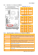
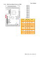
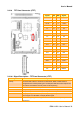
2.4.9 Serial Port 1, 2, 3, 4 Connector (JCOM1-4)
Serial Port 1 (Pin 1-10)
Signal PIN PIN Signal
DCD1 1 2 DSR1
RxD1 3 4 RTS1
TxD1 5 6 CTS1
DTR1 7 8 RI1/+5V/+12V
GND 9 10 NC
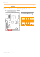
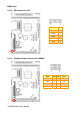
Serial Port 3 (Pin 21-30)
Signal PIN PIN Signal
DCD3 21 22 DSR3
SIN3 23 24 RTS3
SOUT3 25 26 CTS3
DTR3 27 28 RI3/+5V/+12V
GND 29 30 NC
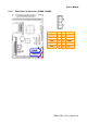
Serial Port 4 (Pin 31-40)
Signal PIN PIN Signal
DCD4 31 32 DSR4
RxD4 33 34 RTS4
SOUT4 35 36 CTS4
DTR4 37 38 RI4/+5V/+12V
GND 39 40 NC
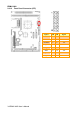
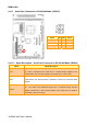
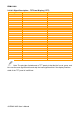
2.4.9.1 Signal Description – Serial Port 1, 2, 3, 4 Connector (JCOM1-4)
Signal Signal Description
TxD
Serial output. This signal sends serial data to the communication link. The signal is
set to a marking state on hardware reset when the transmitter is empty or when
loop mode operation is initiated.
RxD Serial input. This signal receives serial data from the communication link.
DTR
Data Terminal Ready. This signal indicates to the modem or data set that the
on-board UART is ready to establish a communication link.
DSR
Data Set Ready. This signal indicates that the modem or data set is ready to
establish a communication link.
RTS
Request To Send. This signal indicates to the modem or data set that the on-board
UART is ready to exchange data.
CTS
Clear To Send. This signal indicates that the modem or data set is ready to
exchange data.
DCD Data Carrier Detect. This signal indicates that the modem or data set has detected