
Manual

EBM-CX700 Series
34 EBM-CX700 Series User’s Manual
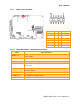
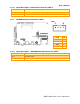
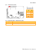
2.4.6 Fan Connector (FAN1, FAN2)
Signal PIN
+5 2
GND 1
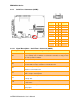
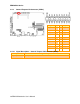
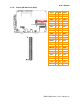
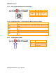
2.4.7 LCD Inverter Connector (JBKL1)
Signal PIN
+12V 1
GND 2
ENBKL 3
VR 4
+5V 5
Note:
For inverters with adjustable Backlight function, it is possible to control the
LCD brightness through the VR signal controlled by JP5. Please see the
JP5 section for detailed circuitry information.
FAN1
FAN
2