
Manual

User’s Manual
EBM-CX700 Series User’s Manual
31
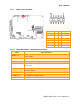
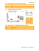
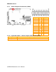
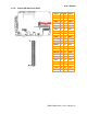
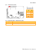
2.4.3 Audio connector (CN1)
Signal PIN
PIN
Signal
LINEOUT_R
1 2 LINEOUT _L
GND 3 4 GND
LIN_R 5 6 LIN_L
Mic In 7 8 Mic Bais
LINEOUT_JD
9 10
LINEIN_JD
MIC_JD 11
12
GND
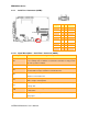
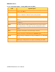
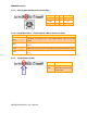
2.4.3.1 Signal Description – Audio Connecter (CN1)
Signal Signal Description
LINEOUT L/R
Left and right speaker output. These are the speaker outputs directly from the
speaker amplifier.
LFE-OUT Low Frequency Effect Out channel (un-amplified)
Line-In L/R Left and right line in signals.
LN L/R
Left and right line out signals. Both signals are capacitor coupled and should have
GND as return.
Mic-in
The MIC signal is used for microphone input. This input is fed to the left
microphone channel.
CEN-OUT Center Out channel (im-amplified)
SURR-OUT L/R Surround Out Feft and Right channel
SPDIF OUT PCM Non-Audio Sony/Philips Digital I/F Output (Internal pulled high).