
Manual

User’s Manual
EBM-A50M User‟s Manual
27
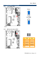
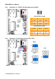
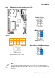
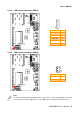
2.4.9 LCD backlight brightness adjustment (JVR)
* Default
Signal
PIN
PIN
Signal
+5V
1
2
DC
VR
3
4
VR
GND
5
6
PWM
Variation Resistor
(Recommended: 4.7KΩ, >1/16W)
Mode1: VR type
Mode 2: DC type*
Note: DC: 0V ~5V
Mode 3: Pulse-Width Modulated type
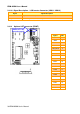
Note:
For inverters with adjustable Backlight function, it is possible to control the LCD brightness
through the VR signal controlled by JBKL1. Please see the JBKL1 section for detailed circuitry
information.