EAX-Q67 Intel® Q67 with Core™ i7/ i5 /i3 ATX Motherboard User’s Manual 3rd Ed – 27 October 2014 Part No: E2047AQ6702R
EAX-Q67 User’s Manual FCC Statement THIS DEVICE COMPLIES WITH PART 15 FCC RULES. OPERATION IS SUBJECT TO THE FOLLOWING TWO CONDITIONS: (1) THIS DEVICE MAY NOT CAUSE HARMFUL INTERFERENCE. (2) THIS DEVICE MUST ACCEPT ANY INTERFERENCE RECEIVED INCLUDING INTERFERENCE THAT MAY CAUSE UNDESIRED OPERATION. THIS EQUIPMENT HAS BEEN TESTED AND FOUND TO COMPLY WITH THE LIMITS FOR A CLASS "A" DIGITAL DEVICE, PURSUANT TO PART 15 OF THE FCC RULES.
EAX-Q67 User’s Manual Life Support Policy Avalue Technology’s PRODUCTS ARE NOT FOR USE AS CRITICAL COMPONENTS IN LIFE SUPPORT DEVICES OR SYSTEMS WITHOUT THE PRIOR WRITTEN APPROVAL OF Avalue Technology Inc. As used herein: 1.
EAX-Q67 User’s Manual Contents Safety Information ............................................................................................................................................... 7 About this guide .................................................................................................................................................. 8 Typography ..........................................................................................................................................
EAX-Q67 User’s Manual 1.8.2 CPU and System fan connectors (CPU_FAN, SYS_FAN,CHA_FAN) .................................................. 35 1.8.3 System Panel (F_PANEL) ...................................................................................................................... 36 1.8.4 ATX power connectors (EATXPWR1).................................................................................................... 37 1.8.5 Serial Port connectors (COM3, COM4, COM5, COM6) ...........................
EAX-Q67 User’s Manual 2.2.2.12.3 Serial Port 5 Configuration .................................................................................................... 63 2.2.2.12.4 Serial Port 6 Configuration .................................................................................................... 64 2.2.2.13 CSM parameters ....................................................................................................................... 65 2.2.2.14 CPU PPM Configuration ...................
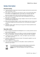
EAX-Q67 User’s Manual Safety Information Electrical safety To prevent electrical shock hazard, disconnect the power cable from the electrical outlet before relocating the system. When adding or removing devices to or from the system, ensure that the power cables for the devices are unplugged before the signal cables are connected. If possible, disconnect all power cables from the existing system before you add a device.
EAX-Q67 User’s Manual Safety Declaration This device complies with the requirements in Part 15 of the FCC rules. Operation is subject to the following two conditions: This device may not cause harmful interference. This device must accept any interference received, including interference that may cause undesired operation. About this guide This user guide contains the information you need when installing and configuring the motherboard.
EAX-Q67 User’s Manual Conventions used in this guide To make sure that you perform certain tasks properly, take note of the following symbols used throughout this manual. DANGER/WARNING: Information to prevent injury to yourself when trying to complete a task. CAUTION: Information to prevent damage to the components when trying to complete a task. IMPORTANT: Instructions that you MUST follow to complete a task. NOTE: Tips and additional information to help you complete a task.
EAX-Q67 User’s Manual Packing List Before you begin installing your single board, please make sure that the following materials have been shipped: 1 x EAX-Q67 ATX Main board 1 x DVD-ROM contains OS drivers 2 x COM cable 2 x SATA cable 1 x I/O Shield If any of the above items is damaged or missing, please contact your retailer.
EAX-Q67 User’s Manual Revision History Revision 1 st Revision History Date First release version for PCB R10 December, 2011 2nd Modified manual descriptions and jumper’s setting 3rd BIOS Setup update Aug, 2012 October, 2014 EAX-Q67 User’s Manual 11
EAX-Q67 User’s Manual Specifications Summary Specifications System nd rd CPU Intel® LGA1155 Socket Supports 2 /3 Generation Core™ i7/i5/i3, Pentium® and Celeron® Processors BIOS AMI 64Mbit SPI System Chipset Intel® Q67 I/O Chipset Nuvoton NCT6776F Memory Four 240-pin UDIMM sockets support up to 16GB dual channel DDR3 1066/ 1333 SDRAM Watchdog Timer Reset: 1 to 255 sec/min per step H/W Status Monitor Monitoring temperature, voltage and cooling fan status.
EAX-Q67 User’s Manual 1 x PS2 KB/MS 2 x COM Port 1 x VGA Back Panel 1 x HDMI 2 x RJ45 port 4 x USB 2.0 1 x 3 Audio Jacks(Line-in/Line-Out/Mic in) Internal I/O Connector 2 x SATAIII connectors , 4 x SATAII connectors 4 x USB connectors support additional 8 USB 2.
EAX-Q67 User’s Manual Block Diagram 14 EAX-Q67 User’s Manual
EAX-Q67 User’s Manual This chapter describes the motherboard features and the new technologies it supports.
EAX-Q67 User’s Manual Chapter 1 - Product Introduction 1.1 Product highlights 1.1.1 Product Overview Supports latest Intel LGA 1155 CPU-socket interface processor, the 2nd Generation Intel® Core i3, i5, i7 desktop processors which are built on 32 nm technologies to provide smart performance and responsiveness on executing tasks, It combines the CPU and GPU to offer fantastic HD media and graphics, especially on 3D gaming experience.
EAX-Q67 User’s Manual -Novell -Green Hills -QNX -LinuxWorks 1.1.3 Key Architecture Features • Supports Intel® LGA1155 Socket Supports 2nd / 3rd Generation Core™ i7/i5/i3, Pentium® and Celeron® Processors . -32nm monolithic die -Integrated Gfx (Intel® HD Graphics 3000/2000) & memory controller -4 &2 Cores, up to 6MB LLC -HW accelerated video CODECs - Compatible with high speed DDR3-1333 -PCIe* (CPU): Gen 2.
EAX-Q67 User’s Manual - Six SATA ports (4 port of Gen 2.0 and 2 ports of Gen 3.0) support RAID 0,1, 5, 10 - Gigabit Ethernet Media Access Controller (GbE MAC) IPv4 and IPv6 Checksum Offload - High Definition Audio - USB: Gen 2.0, up to 12 ports - SMBus 2.0 - LPC Bus Supports SPI devices - Hardware Monitor Fan control, Voltage, Temp Watchdog timer 1.2 Before you Proceed Take note of the following precautions before you install motherboard components or change any motherboard settings.
EAX-Q67 User’s Manual 1.3 Motherboard Overview Before you install the motherboard, study the configuration of your chassis to ensure that the motherboard fits into it. Refer to the chassis documentation before installing the motherboard. Make sure to unplug the power cord before installing or removing the motherboard. Failure to do so can cause you physical injury and damage motherboard components. 1.3.
EAX-Q67 User’s Manual 1.3.3 Motherboard Layout 1.3.
EAX-Q67 User’s Manual Jumpers Label Function Note JCMOS1 Clear CMOS 3 x 1 header, pitch 2.54mm PSON1 AT/ATX Mode Select 3 x 1 header, pitch 2.54mm Rear Panel Connector Label Function Note KBMS PS/2 Keyboard and Mouse 6-pin Mini-Din COM1 COM1 Connector D-sub 9-pin, male COM2 COM2 Connector D-sub 9-pin, male VGA1 VGA Port D-sub 15-pin, female HDMI1 HDMI Port HDMI 1.3 19-pin LAN1USB12 RJ-45 Ethernet Connector x 1 USB 2.0 Connector x 2 LAN2USB34 RJ-45 Ethernet Connector x 1 USB 2.
EAX-Q67 User’s Manual 1.4 Central Processing Unit (CPU) The motherboard comes with a surface mount LGA1155 socket designed for the Intel® Core™ i7/ i5/ i3 processor in the 1155-land package. Your boxed Intel® Core™ i7/ i5/ i3 LGA1155 processor package should come with installation instructions for the CPU, fan and heatsink assembly. If the instructions in this section do not match the CPU documentation, follow the latter.
EAX-Q67 User’s Manual 1.4.1 Installing the CPU 1. Locate the CPU socket on the motherboard. Before installing the CPU, make sure that the socket box is facing towards you and the load lever is on your left. 2. Press the load lever with your thumb (A), then move it to the left (B) until it is released from the retention tab. To prevent damage to the socket pins, do not remove the PnP cap unless you are installing a CPU.
EAX-Q67 User’s Manual 3. Lift the Load lever with your thumb and forefinger to around 180º angle (A), then pull the PnP cap from the CPU socket to remove (B). B A 4. Position the CPU over the socket, making sure that the gold triangle is on the top-left corner of the socket then fit the socket alignment key into the CPU notch. 5. Pull back the load lever , then push the load lever (A) until it snaps into the retention tab. A The CPU fits in only one correct orientation.
EAX-Q67 User’s Manual 1.4.2 Installing the CPU Heatsink and Fan Intel® Core™ i7/ i5/ i3 LGA1155 processor requires a specially designed heatsink and fan assembly to ensure optimum thermal condition and performance. Install the motherboard to the chassis before you install the CPU fan and heatsink assembly. When you buy a boxed Intel® Core™ i7/ i5/ i3 LGA1155 processor, the package includes the CPU fan and heatsink assembly.
EAX-Q67 User’s Manual Orient the heatsink and fan assembly such that the CPU fan cable is closest to the CPU fan connector. Make sure each fastener is oriented as shown, with the narrow groove directed outward. 2. Push down two fasteners at a time in a diagonal sequence to secure the heatsink and fan assembly in place. A A B B B A B A 3. Connect the CPU fan cable to the connector on the motherboard labeled CPU_FAN. CPU_FAN CPU FAN Do not forget to connect the fan cables to the fan connectors.
EAX-Q67 User’s Manual 1.4.3 Uninstalling the CPU Heatsink and Fan To uninstall the CPU heatsink and fan: 1. Disconnect the CPU fan cable from the connector on the motherboard. 2. Rotate each fastener counterclockwise 2. Pull up two fasteners at a time in a diagonal sequence to disengage the heatsink and fan assembly from the motherboard. 4. Carefully remove the heatsink and fan assembly from the motherboard.
EAX-Q67 User’s Manual 5. Rotate each fastener clockwise to ensure correct orientation when reinstalling. 1.5 System Memory 1.5.1 Overview The motherboard comes with four 240-pin Double Data Rate 3 (DDR3) Dual Inline Memory Modules (DIMM) sockets. A DDR3 module has the same physical dimensions as a DDR DIMM but has a 240-pin footprint compared to the 240-pin DDR2 DIMM. DDR3 DIMMs are notched differently to prevent installation on a DDR2 DIMM socket.
EAX-Q67 User’s Manual 1.5.2 Memory Configurations You may install 1 GB, 2 GB , and 4 GB unbuffered ECC or non-ECC DDR3 DIMMs into the DIMM sockets using the memory configurations in this section. IF you installed four 1GB memory modules, the system may detect less than 3GB of total memory because of address space allocation for other critical functions.
EAX-Q67 User’s Manual 3. Firmly insert the DIMM into the socket until the retaining clips snap back in place and the DIMM is properly seated. A DDR3 DIMM is keyed with a notch so that it fits in only one direction. DO NOT force a DIMM into a socket to avoid damaging the DIMM. The DDR3 DIMM sockets do not support DDR DIMMs. DO NOT install DDR2 DIMMs to the DDR3 DIMM socket. Make sure to unplug the power supply before adding or removing DIMMs or other system components.
EAX-Q67 User’s Manual 1.6 Expansion Card In the future, you may need to install expansion cards. The following sub-sections describe the slots and the expansion cards that they support. Make sure to unplug the power cord before adding or removing expansion cards. Failure to do so may cause you physical injury and damage motherboard components. 1.6.1 Installing an Expansion Card 1.
EAX-Q67 User’s Manual 1.6.4 PCIeX4 Raid card This motherboard supports one PCI Express x4 slot that complies with the PCI Express specifications. The following shows a RAID card installed on the PCI Express x 4 slot. 1.6.5 PCIeX1 LAN card This motherboard supports one PCI Express x 1 slot that complies with the PCI Express specifications. The following figure shows a LAN card installed on the PCI Express x 1 slot. 1.6.
EAX-Q67 User’s Manual 1.7 Jumpers 1.7.1 Clear CMOS (JCMOS1) This jumper allows you to clear the Real Time Clock (RTC) RAM in CMOS. You can clear the CMOS memory of date, time, and system setup parameters by erasing the CMOS RTC RAM data. The onboard button cell battery powers the RAM data in CMOS, which includes system setup information such as system passwords. To erase the RTC RAM: 1. Turn OFF the computer and unplug the power cord. 2. Remove the onboard battery. 3.
EAX-Q67 User’s Manual 1.7.2 AT/ATX Power Mode Select (PSON1) This jumper allows you to select ATX Mode or AT mode . ATX MODE (Default) AT MODE 1.8 Connectors 1.8.1 Rear panel connectors 1. PS/2 mouse port (green). This port is for a PS/2 mouse. 2. PS/2 keyboard port (purple). This port is for a PS/2 keyboard. 3. Serial connector. This 9-pin COM1 port is for serial devices. 4. Serial connector. This 9-pin COM2 port is for serial devices. 5. VGA port. This 15-pin VGA port connects to a VGA monitor. 6.
EAX-Q67 User’s Manual 8. USB 2.0 ports 1 ~ 4. These four 4-pin Universal Serial Bus (USB) ports are available for connecting USB 2.0 devices. 9. Line In port (light blue). This port connects a tape, CD, DVD player, or other audio sources. 10 Line Out port (lime). This port connects a headphone or a speaker. In 4-channel, 6-channel, and 8-channel configuration, the function of this port becomes Front Speaker Out. 11. Microphone port (pink). This port connects a microphone. 1.8.
EAX-Q67 User’s Manual 1.8.3 System Panel (F_PANEL) This connector is for a chassis-mounted front panel I/O module that supports ,power on /reset switch and HDD / Power LED indicate. F_PANEL ATX Power Button/Soft-off Button (Pin 6-8 PWRBT) This 2-pin connector is for the system power button. Pressing the power button turns the system on or puts the system in sleep or soft-off mode depending on the BIOS settings.
EAX-Q67 User’s Manual 1.8.4 ATX power connectors (EATXPWR1) The connector is for ATX power supply plugs. The power supply plugs are designed to fit these connectors in only one orientation. Find the proper orientation and push down firmly until the connectors completely fit. EATXPWR1 ATX12V1 Use of a PSU with a higher power output is recommended when configuring a system with more power-consuming devices. The system may become unstable or may not boot up if the power is inadequate.
EAX-Q67 User’s Manual 1.8.6 Digital IO Connector (JDIO1) This connector is for 8-bit General purpose I/O function. JDIO1 1.8.7 Audio Mic.-In & Line-Out Connector (FPAUD1) This connector is for a chassis-mounted front panel audio I/O module that supports either HD Audio or legacy AC ‘97 (optional) audio standard. FPAUD1 1.8.8 Internal KB/MS connector (KBMS2) This connector is for internal KB/MS.
EAX-Q67 User’s Manual 1.8.9 Digital Audio connector (SPDIF_OUT) This connector is for the S/PDIF audio module to allow digital sound output. Connect one end of the S/PDIF audio cable to this connector and the other end to the S/PDIF module. SPDIF_OUT 1.8.10 TPM Connector (TPM) TPM 1.CLK33M_LPC 3.LPC_FRAME# 5.PLTRST_SIO# 7.LPC_AD3 9.+V3.3 11.LPC_AD0 13.NC 15.+V3.3_DUAL 17.GND 19.LPCPD# 2.GND 4.NC 6.NC 8.LPC_AD2 10.LPC_AD1 12.GND 14.NC 16.PCI_SERIRQ 18.GND 20.NC 1.8.11 Serial ATA 3.
EAX-Q67 User’s Manual 1.8.12 Serial ATA II Connector (SATA3 , SATA4 , SATA5, SATA6 ) These connectors support SATA 2.0 and are for the Serial ATA signal cables for Serial ATA hard disk drives. SATA3、SATA4、SATA5、SATA6 Connect the right-angle side of SATA signal cable to SATA device. Or you may connect the right-angle side of SATA cable to the onboard SATA port to avoid mechanical conflict with large graphics cards. 1.8.13 USB connectors (USB56, USB78, USB910, USB1112,) These connectors are for USB 2.
EAX-Q67 User’s Manual This chapter tells how to change the system settings through the BIOS Setup menus. Detailed descriptions of the BIOS parameters are also provided.
EAX-Q67 User’s Manual Chapter 2 - BIOS Setup 2.1 BIOS Setup Program This motherboard supports a programmable firmware chip that you can update using the provided utility. Use the BIOS Setup program when you are installing a motherboard, reconfiguring your system, or prompted to “Run Setup.” This section explains how to configure your system using this utility. Even if you are not prompted to use the Setup program, you can change the configuration of your computer in the future.
EAX-Q67 User’s Manual 2.1.1 Legend Box The keys in the legend bar allow you to navigate through the various setup menus Key(s) ← →↓↑ Function Description Move +- Value Enter Select ESC Exit F1 General Help F2 Previous Values F3 Optimized Defaults F4 Sace & Exit Setup 2.1.2 List Box This box appears only in the opening screen. The box displays an initial list of configurable items in the menu you selected. 2.1.3 Sub-menu Note that a right pointer symbol appears to the left of certain fields.
EAX-Q67 User’s Manual 2.2 BIOS Menu Screen 2.2.1 Main Menu This section allows you to record some basic hardware configurations in your computer and set the system clock. 2.2.1.1 System Date Use the system date option to set the system date. Manually enter the day, month and year. 2.2.1.2 System Time Use the system time option to set the system time. Manually enter the hours, minutes and seconds.
EAX-Q67 User’s Manual 2.2.2 Advanced Menu This section allows you to configure your CPU and other system devices for basic operation through the following sub-menus. 2.2.2.
EAX-Q67 User’s Manual Item Options Above 4G Decoding Disabled[Default], Enabled PCI Latency Timer 32 PCI Bus Clocks[Default] 64 PCI Bus Clocks 96 PCI Bus Clocks 128 PCI Bus Clocks 160 PCI Bus Clocks 192 PCI Bus Clocks 224 PCI Bus Clocks 248 PCI Bus Clocks 2.2.2.2 APCI Settings 46 EAX-Q67 User’s Manual Description Enables or Disables 64bit capable Devices to be Decoded in Above 4G Address Space (Only if System Supports 64 bit PCI Decoding). Value to be programmed into PCI Latency Timer Register.
EAX-Q67 User’s Manual EAX-Q67 User’s Manual 47
EAX-Q67 User’s Manual 48 EAX-Q67 User’s Manual
EAX-Q67 User’s Manual Item Options APCI Sleep State S1 only(CPU Stop Clock) [Default] S3 only(Suspend to RAM) S3 Video Repost Disabled[Default] Enabled Enable or Disable S3 Video Repost. Resume On RTC Alarm Disabled[Default] Enabled Enable or disable System wake on alarm event. When enabled, System will wake on the hr::min::sec specified.
EAX-Q67 User’s Manual 2.2.2.4 CPU Configuration Use the CPU configuration menu to view detailed CPU specification and configure the CPU.
EAX-Q67 User’s Manual Item Active Processor Cores Intel Virtualization Technology Options All[Default], 1 2 3 Disabled, Enabled[Default] Description Number of cores to enable in each processor package. When enabled, a VMM can utilize the additional hardware capabilities provided by Vanderpool Technology. 2.2.2.5 SATA Configuration It allows you to select the operation mode for SATA controller.
EAX-Q67 User’s Manual Item SATA Controller(s) SATA Mode Selection 52 EAX-Q67 User’s Manual Options Enabled[Default] Disabled IDE[Default] AHCI RAID Description Enable or disable SATA Device. Determines how SATA controller(s) operate.
EAX-Q67 User’s Manual 2.2.2.6 Intel TXT (LT) Configuration 2.2.2.
EAX-Q67 User’s Manual 2.2.2.8 AMT Configuration Intel AMT allows hardware-based remote management, security, power-management, and remote-configuration features.
EAX-Q67 User’s Manual Item Options Intel AMT Enabled[Default] Disabled Un-Configure ME Enabled Disabled[Default] Description Enable/Disable Intel ® Active Management Technology BIOS Extension. Note: iAMT H/W is always enabled. This option just controls the BIOS extension execution. If enabled, this requires additional firmware in the SPI device OEMFlag Bit 15: Un-Configure ME without password. 2.2.2.
EAX-Q67 User’s Manual Item Options Legacy USB Support Enabled[Default] Disabled Auto Generic-SD/MMC 1.00 Auto[Default] Floppy Forced FDD Hard Disk CD-ROM 56 EAX-Q67 User’s Manual Description Enables Legacy USB support. AUTO option disables legacy support if no USB devices are connected. DISABLE option will keep USB devices available only for EFI applications. Mass storage device emulation type. ‘AUTO’ enumerates devices according to their media format.
EAX-Q67 User’s Manual 2.2.2.10 Super IO Configuration You can use this item to set up or change the Super IO configuration for serial ports. Please refer to 2.2.2.10.1 and 2.2.2.10.2 for more information. Item Watch Dog Timer Options Disabled [Default] Enabled Description Enables or Disabled Watch Dog Timer function.
EAX-Q67 User’s Manual 2.2.2.10.1 Serial Port 1 Configuration Item Serial Port Change Settings Option Enabled[Default], Disabled Auto[Default] IO=3F8h; IRQ=4, IO=3F8h; IRQ=3,4,5,6,7,9,10,11,12; IO=2F8h; IRQ=3,4,5,6,7,9,10,11,12; IO=3E8h; IRQ=3,4,5,6,7,9,10,11,12; IO=2E8h; IRQ=3,4,5,6,7,9,10,11,12; 2.2.2.10.2 Serial Port 2 Configuration 58 EAX-Q67 User’s Manual Description Enable or Disable Serial Port (COM). Select an optimal setting for Super IO device.
EAX-Q67 User’s Manual Item Serial Port Change Settings Option Enabled[Default], Disabled Description Enable or Disable Serial Port (COM). Auto[Default] IO=2F8h; IRQ=3 IO=3F8h; IRQ=3,4,5,6,7,9,10,11,12; IO=2F8h; IRQ=3,4,5,6,7,9,10,11,12; IO=3E8h; IRQ=3,4,5,6,7,9,10,11,12; IO=2E8h; IRQ=3,4,5,6,7,9,10,11,12; Select an optimal setting for super IO device. 2.2.2.11 H/W Monitor 2.2.2.11.
EAX-Q67 User’s Manual Item Smart Fan Function Option Enabled[Default], Disabled Description Smart Fan Function Enable/Disable. 2.2.2.11.1.1 Smart Fan Mode Configuration Item SYS Smart Fan Mode 60 EAX-Q67 User’s Manual Option Manual Mode[Default], Thermal Cruise Mode Description SYS Smart Fan Mode.
EAX-Q67 User’s Manual SYSFAN expect PWM Output/DC Voltag 0-255 CPU Smart Fan Mode Manual Mode[Default], Thermal Cruise Mode CPU expect PWM Output/DC Voltage 0-255 Chassis Smart Fan Mode Manual Mode[Default], Thermal Cruise Mode Chassis expect PWM Output/DC Voltage 0-255 System FAN expect PWM Output/DC Voltage. CPU Smart Fan Mode. CPU expect PWM Output/DC Voltage. Chassis Smart Fan Mode. Chassis expect PWM Output/DC Voltage. 2.2.2.
EAX-Q67 User’s Manual 2.2.2.12.1 Serial Port 3 Configuration Item Serial Port Change Settings Option Enabled[Default], Disabled Auto[Default] IO=3E8h; IRQ=5, IO=3F8h; IRQ=5,10; IO=2F8h; IRQ=5,10; IO=3E8h; IRQ=5,10; IO=2E8h; IRQ=5,10; 2.2.2.12.2 Serial Port 4 Configuration 62 EAX-Q67 User’s Manual Description Enable or Disable Serial Port (COM). Select an optimal setting for Super IO device.
EAX-Q67 User’s Manual Item Serial Port Change Settings Option Enabled[Default], Disabled Description Enable or Disable Serial Port (COM). Auto[Default] IO=2E8h; IRQ=5, IO=3F8h; IRQ=5,10; IO=2F8h; IRQ=5,10; IO=3E8h; IRQ=5,10; IO=2E8h; IRQ=5,10; Select an optimal setting for super IO device. 2.2.2.12.3 Serial Port 5 Configuration Item Serial Port Change Settings Option Enabled[Default], Disabled Description Enable or Disable Serial Port (COM).
EAX-Q67 User’s Manual 2.2.2.12.4 Serial Port 6 Configuration Item Serial Port Change Settings 64 EAX-Q67 User’s Manual Option Enabled[Default], Disabled Description Enable or Disable Serial Port (COM). Auto[Default] IO=2F0h; IRQ=10, IO=3F8h; IRQ=5,10; IO=2F8h; IRQ=5,10; IO=3E8h; IRQ=5,10; IO=2E8h; IRQ=5,10; IO=2E0h; IRQ=5,10; IO=2F0h; IRQ=5,10; Select an optimal setting for super IO device.
EAX-Q67 User’s Manual 2.2.2.
EAX-Q67 User’s Manual Item Launch PXE OpROM policy Launch Storage OpROM policy Other PCI device ROM priority 66 EAX-Q67 User’s Manual Options Disabled[Default] Enabled Disabled Enabled[Default] UEFI OpROM[Default] Legacy OpROM Description Controls the execution of UEFI and Legacy PXE OpROM. Controls the execution of UEFI and Legacy Storage OpROM. For PCI devices other than Network, Mass storage or Video defines which OpROM to launch.
EAX-Q67 User’s Manual 2.2.2.
EAX-Q67 User’s Manual 68 EAX-Q67 User’s Manual
EAX-Q67 User’s Manual Item EIST Turbo Mode CPU C3/6/7 Report ACPI T State Options Disabled Enabled[Default] Disabled Enabled[Default] Disabled Enabled[Default] Disabled[Default] Enabled Description Enable/Disable Intel SpeedStep. Turbo Mode. Enable/Disable CPU C3(ACPI C2)/ C6(ACPI C3)/ C7(ACPI C3) report to OS. Enable/Disable ACPI T state support.
EAX-Q67 User’s Manual 2.2.3 Chipset 2.2.3.
EAX-Q67 User’s Manual EAX-Q67 User’s Manual 71
EAX-Q67 User’s Manual Item LAN1 Controller Wake on LAN1 LAN2 Controller PCIeX4/1 Speed Restore AC Power Loss 72 EAX-Q67 User’s Manual Options Disabled Enabled[Default] Disabled Enabled[Default] Disabled Enabled[Default] Auto[Default] Gen1 Gen2 Power Off[Default] Power On Last State Description Enable or disable onboard NIC. Enable or disable integrated LAN to wake the system. (The Wake On LAN cannot be disabled if ME is on at Sx state.) Control the PCI Express Root Port.
EAX-Q67 User’s Manual 2.2.3.1.1 USB Configuration Item EHCI1/2 USB Ports Per-Port Disable Control Option Enabled[Default], Disabled Description Control the USB EHCI (USB2.0) functions. One EHCI controller must always be enabled. Enabled Disabled[Default], Control each of the USB ports (0~13) disabling. 2.2.3.1.
EAX-Q67 User’s Manual Item Option Azalia Disabled Enabled Auto[Default] Azalia HDMI codec Port D Disabled Enabled[Default], 2.2.3.2 Description Control Detection of the Azalia device. Disabled = Azalia will be unconditionally disabled. Enabled = Azalia will be unconditionally Enabled. Auto = Azalia will be enabled if present, disabled otherwise. Enable or disable internal HDMI codec Port for Azalia.
EAX-Q67 User’s Manual 2.2.3.2.
EAX-Q67 User’s Manual 76 EAX-Q67 User’s Manual
EAX-Q67 User’s Manual Item Primary Display Internal Graphics Option Auto[Default], IGFX PEG PCI Auto[Default] Disabled Enabled Description Select which of IGFX/PEG/PCI Graphics device should be Primary Display Or select SG for Switchable Gfx. Keep IGD enabled based on the setup options. DVMT Pre-Allocated 64M[Default]/96M/128M/160M/ 192M/224M/256M/288M/320M Select DVMT 5.0 Pre-Allocated (Fixed) Graphics Memory size used by the Internal Graphics Device.
EAX-Q67 User’s Manual 2.2.3.2.
EAX-Q67 User’s Manual Item PEG0 – Gen X PEG0 ASPM Enable PEG Option Auto[Default] Gen1 Gen2 Gen3 Disabled[Default] Auto ASPM L0s ASPM L1 ASPM L0sL1 Disabled Enabled Auto[Default] Description Configure PEG0 B0:D1:F0 Gen1-Gen3. Control ASPM support for the PEG: Device 1 Function 0. This has no effect if PEG is not the currently active device. To enable or disable the PEG. 2.2.3.2.
EAX-Q67 User’s Manual 2.2.
EAX-Q67 User’s Manual Item Option Setup Prompt Timeout 1 ~ 65535 On Off[Default] Disabled Enabled[Default] Bootup NumLock State Quiet Boot Boot Option #1/2/3 2.2.5 Description Number of seconds to wait for setup activation key. 65535(0xFFFF) means indefinite waiting. Select the Keyboard NumLock state Enables or disables Quiet Boot option Set the system boot order. Save and exit 2.2.5.1 Save Changes and Exit Exit system setup after saving the changes. 2.2.5.