ARC-1209 12.1" Intel® Atom™ SoC Processor E3845 Fanless Rugged Touch Panel PC with IET Expansion Quick Reference Guide 2nd Ed – 13 May 2015 Copyright Notice Copyright 2015 Avalue Technology Inc., ALL RIGHTS RESERVED. Part No.
ARC-1209 FCC Statement THIS DEVICE COMPLIES WITH PART 15 FCC RULES. OPERATION IS SUBJECT TO THE FOLLOWING TWO CONDITIONS: (1) THIS DEVICE MAY NOT CAUSE HARMFUL INTERFERENCE. (2) THIS DEVICE MUST ACCEPT ANY INTERFERENCE RECEIVED INCLUDING INTERFERENCE THAT MAY CAUSE UNDESIRED OPERATION. THIS EQUIPMENT HAS BEEN TESTED AND FOUND TO COMPLY WITH THE LIMITS FOR A CLASS "A" DIGITAL DEVICE, PURSUANT TO PART 15 OF THE FCC RULES.
Quick Reference Guide Content 1. Getting Started ........................................................................................................ 5 1.1 1.2 1.3 1.4 Safety Precautions .................................................................................................... 5 Packing List ............................................................................................................... 5 System Specifications ..................................................................
ARC-1209 2.7.8 ARC-BYT DB-H ..................................................................................................................... 32 2.7.9 ARC-BYT DB-K ..................................................................................................................... 32 2.8 ARC-BYT DB-A/B/C/D/E/F/G/H/K Connector list .................................................... 33 2.8.1 ARC-BYT DB-A ...............................................................................................
Quick Reference Guide 1. Getting Started 1.1 Safety Precautions Warning! Always completely disconnect the power cord from your chassis whenever you work with the hardware. Do not make connections while the power is on. Sensitive electronic components can be damaged by sudden power surges. Only experienced electronics personnel should open the PC chassis. Caution! Always ground yourself to remove any static charge before touching the CPU card.
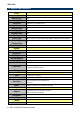
ARC-1209 1.3 System Specifications Panel LCD Size Display Type 12.1", 4:3 XGA Resolution 1024 x 768 Pixel pitch 0.1905 mm (H) x 0.1905 mm (V) Luminance 600 cd/m² Contrast ratio 700 Viewing angle 80 (U), 80 (D), 80 (L), 80 (R) Response time 16ms Backlight LED Touch Type Touch Light Transmission Touch Controller 5 Wires resistive (P-cap available with MOQ in standard shock & vibration) 80% Onboard USB touch (PenMount) System SBC ARC-BYT Processor Intel® Atom™ E3845 4-Core 1.
Quick Reference Guide Audio Interface Speaker Out Speaker Output 2 x 1W Ethernet Chipset Ethernet Interface Lan Port 2 x Intel® I210IT 10/100/1000 Base-Tx GbE compatible 2 x RJ-45 Ethernet Power Connector Lockable DC Jack Power Requirement +12V ~ +26V Power Type Adapter AT/ATX (ATX is default setting) Input: 100 ~ 240Vac/ 50 ~ 60Hz Output: 60W Adapter (12V @ 5A Adapter) Ethernet System Fan Fanless Construction - Front Silver Aluminum Construction – Rear Black Dimension Weight Operating Temperatu
ARC-1209 (ACC-ARC-COM-3R) ARC-BYT DB-K 2 x RS-232 + LAN Kit for ARC Series (ACC-ARC-COM-4R) ARC-BYT DB-E 12-bit GPIO + 2-pin CAN Bus Kit for ARC Series (ACC-ARC-GPIO-1R) ARC-BYT DB-F OBDII - CAN Bus Kit for ARC Series (Small Vechile) (ACC-ARC-OBDII-1R) ARC-BYT DB-F OBDII - CAN Bus Kit for ARC Series (Large Vechile) (ACC-ARC-OBDII-2R) ARC-BYT DB-F OBDII - CAN Bus Kit for ARC Series (Special Large Vechile) (ACC-ARC-OBDII-3R) Note: Specifications are subject to change without notice.
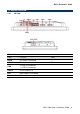
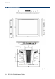
Quick Reference Guide 1.4 System Overview 1.4.1 I/O View Connectors Label Function DC-IN DC Power-in connector COM1/2 Serial port 1/2 connector USB 3 x USB 2.0 connector 1 x USB 3.
ARC-1209 1.
Quick Reference Guide 2. Hardware Configuration For advanced information, please refer to: 1- ARC-BYT, ARC-BYT DB-A/B/C/D/E/F/G/H/K included in this manual. Note: If you need more information, please visit our website: http://www.avalue.com.
ARC-1209 2.1 ARC-1209 connector mapping 2.1.1 Serial port 1 connector (COM1) RS-232 Signal RS-485 Signal 2.1.
Quick Reference Guide 2.2 Installing Hard Disk & Memory Step 1. Memory Installation: Remove 3 screws to release the chassis cover, and remove it. Step 2.1 Insert the SODIMM into the memory socket. Step 2.2 Re-assemble your system back through previous steps to complete the installation.
ARC-1209 Step 3. HDD Installation: Insert the HDD into the Drive Bay and fasten 2 screws.
Quick Reference Guide 2.3 Installing ARC-BYT DB Step 1. Unfasten 2 screws of the HDD bracket and take it off. Step 2. Remove 4 screws to release the chassis cover, and remove it.
ARC-1209 Step 2.1 Insert the ARC-BYT DB into the socket and fasten 3 screws. Step 2.
Quick Reference Guide 2.
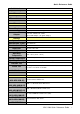
ARC-1209 2.5 ARC-BYT Jumper and Connector list Jumper Label Function Note JCMOS1 Clear CMOS 3 x 1 header, pitch 2.00mm JRI1/2 Serial port 1/2 pin9 signal select 3 x 2 header, pitch 2.00mm JP1 Serial port 1 in RS-422/485 mode 4 x 3 header, pitch 2.00mm JVR1 LCD backlight brightness adjustment 3 x 1 header, pitch 2.00mm JAT1 AT/ATX Input power select 3 x 1 header, pitch 2.00mm Label Function Note SODIMM1 204-pin DDR3L SODIMM socket JBKL1 LCD Inverter connector 5 x 1 wafer, pitch 2.
Quick Reference Guide 2.6 ARC-BYT Jumpers & Connectors settings 2.6.1 Clear CMOS (JCMOS1) Protect* Clear CMOS *Default 2.6.
ARC-1209 2.6.3 LCD backlight brightness adjustment (JVR1) PWM Mode* DC Mode * Default 2.6.
Quick Reference Guide 2.6.5 Serial port 1 in RS-422/485 mode (JP1) PIN Signal PIN Signal PIN Signal 1 NDCDA# 2 COM1-1 3 485_422TX1- 4 NRXDA 5 COM1-2 6 485_422TX1+ 7 NTXDA 8 COM1-3 9 422RX1+ 10 NDTRA# 11 COM1-4 12 422RX1- * Default 2.6.6 LCD Inverter connector (JBKL1) Signal PIN +12V 1 GND 2 BKLEN 3 VBRIGHT 4 +5V 5 Note: For inverters with adjustable Backlight function, it is possible to control the LCD brightness through the VR signal controlled by JVR.
ARC-1209 2.6.7 2.6.8 22 On-board header for USB2.
Quick Reference Guide 2.6.
ARC-1209 2.6.10 2.6.11 24 Battery connector (BT1) Signal PIN +3.
Quick Reference Guide 2.6.12 2.6.13 AMPLIFIER_L (JSPL1) Signal PIN SPK_L+ 1 SPK_L- 2 LPC connector (JLPC1) Signal PIN PIN Signal GND 10 9 LPC_SERIRQ LPC_PORT80_CLK 8 7 LPC_AD3 LPC_FRAME# 6 5 LPC_AD2 LPC_PORT80_RST# 4 3 LPC_AD1 +3.
ARC-1209 2.6.14 SPI connector (JSPI1) Signal 2.6.
Quick Reference Guide 2.6.16 Miscellaneous setting connector (JFP1) Signal PIN 1 PWBT 2 3 RST# 4 2.6.
ARC-1209 2.6.
Quick Reference Guide 2.6.
ARC-1209 2.7 ARC-BYT DB-A/B/C/D/E/F/G/H/K Overviews 2.7.1 ARC-BYT DB-A 2.7.2 ARC-BYT DB-B 2.7.
Quick Reference Guide 2.7.4 ARC-BYT DB-D 2.7.5 ARC-BYT DB-E 2.7.
ARC-1209 2.7.7 ARC-BYT DB-G 2.7.8 ARC-BYT DB-H 2.7.
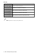
Quick Reference Guide 2.8 ARC-BYT DB-A/B/C/D/E/F/G/H/K Connector list 2.8.1 ARC-BYT DB-A Connectors Label Function A_JUSB1~4 USB3.0 connector 1~4 A_JB2B1 B2B connector 2.8.2 Note ARC-BYT DB-B Connectors Label Function Note B_LINE_OUT1 Line-out audio jack B_LINE_IN1 Line-in audio jack B_MIC_IN1 Mic-in audio jack B_JHDMI1 HDMI connector B_JB2B1 B2B connector 2.8.
ARC-1209 For user update FW 3 x 1 header, pitch 2.00mm Label Function Note E_GPIO1 General purpose I/O connector E_CN1 For user update FW E_CAN1 CAN Bus connector E_JB2B1 B2B connector E_JBOOT0 Connectors 2.8.6 5 x 1 header, pitch 2.54mm ARC-BYT DB-F Connectors Label Function Note F_CAN1 CAN Bus connector 1 7 x 2 header, pitch 2.00mm F_CAN2 CAN Bus connector 2 F_JB2B1 B2B connector 2.8.
Quick Reference Guide I_JLAN1 RJ-45 Ethernet I_COM1/2 Serial Port 1/2 connector I_JB2B1 B2B connector DB-9 male connector ARC-1209 Quick Reference Guide 35
ARC-1209 2.9 ARC-BYT DB-E Jumpers & Connectors settings 2.9.1 CAN2.0 Switch (E_JCAN20) CAN2.0A (11-bit)* CAN2.0B (29-bit) *Default 2.9.
Quick Reference Guide 2.9.3 For user update FW (E_JIAP1) Default* For user update FW *Default 2.9.4 For user update FW (E_CN1) Signal PIN +3.
ARC-1209 2.10 ARC-BYT DB-F Connectors settings 2.10.1 CAN Bus connector 1 (F_CAN1) Signal PIN PIN CAN_PWR 1 2 CAN_8 CAN_IND 3 4 CAN_9 GND 5 6 BAT_GND CAN_WAKE 7 8 CAN_11 UART_RXD_1_F 9 10 CAN_12 UART_TXD_1_F 11 12 CAN_13 +5V 13 14 CAN_14 2.11 ARC-BYT DB-H Jumpers settings 2.11.
Quick Reference Guide 3.
ARC-1209 3.1 Introduction The BIOS setup program allows users to modify the basic system configuration. In this following chapter will describe how to access the BIOS setup program and the configuration options that may be changed. 3.2 Starting Setup The AMI BIOS™ is immediately activated when you first power on the computer. The BIOS reads the system information contained in the NVRAM and begins the process of checking out the system and configuring it.
Quick Reference Guide 3.3 Using Setup In general, you use the arrow keys to highlight items, press to select, use the PageUp and PageDown keys to change entries, press for help and press to quit. The following table provides more detail about how to navigate in the Setup program using the keyboard.
ARC-1209 3.4 Getting Help Press F1 to pop up a small help window that describes the appropriate keys to use and the possible selections for the highlighted item. To exit the Help Window press or the F1 key again. 3.5 In Case of Problems If, after making and saving system changes with Setup, you discover that your computer no longer is able to boot, the AMI BIOS supports an override to the NVRAM settings which resets your system to its defaults.
Quick Reference Guide 3.6 BIOS setup Once you enter the Aptio Setup Utility, the Main Menu will appear on the screen. The Main Menu allows you to select from several setup functions and exit choices. Use the arrow keys to select among the items and press to accept and enter the sub-menu. 3.6.1 Advanced Menu This section allows you to configure your CPU and other system devices for basic operation through the following sub-menus. 3.6.1.