
User Manual


AW5800mT User’s Manual
PAGE 4
Technical support :: (650) 384.0000
www.avalanwireless.com
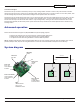
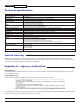
LED display
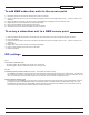
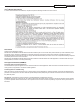
Initial setup
1) Select the module that will operate as the access point (AP) and set DIP switch 1 ON to enable AP operation.
2) Plug in the access point.
— The LINK QUALITY LEDs will blink sequentially showing that the module is hunting for a subscriber unit (SU) to share keys
— with.
3) Plug in a subscriber unit.
— The LINK QUALITY LEDs will blink sequentially showing the module is hunting for an AP to supply a network key.
4) Connect an Ethernet cable from the AP to the SU and the units will automatically exchange keys over the Ethernet cable (key
exchange will not work through a switch or hub — crossover cables are required).
— On the AP, the LINK QUALITY LEDs will still show that the module is still in “key exchange mode” and the RF TX LED will be
— lit showing that the keys exchanged successfully — ignore the other LEDs.
— On the SU, the LINK QUALITY LEDs no longer blink sequentially and will show that the module has stopped hunting and now
— has a slowly blinking pulse on one of the GREEN LINK QUALITY LEDs — ignore the other LEDs.
5) Repeat steps 3 and 4 until all SUs are successfully programmed.
6) Power cycle all modules for the new keys to take effect.
7) Deploy the modules.
n
n
n
n