
User's Manual
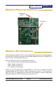

MOD090-LP
User’s Manual
PAGE 10
Technical support (650) 384-0000 www.avalanwireless.com
D
7
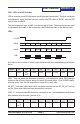
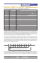
and the Stop Bit, but this is rarely done anymore.
UART Mode LEDs and DIPs:
With the UART rmware running, the LED denitions are the same as for SPI mode
and provide diagnostic information if desired.
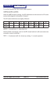
The DIP switch denitions are slightly different:
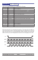
b7 b6 b5 b4 b3 b2 b1 b0
Byte3 DCH3 DCH2 DCH1 DCH0 MODE -
Byte4 TEST
MODE: 1 = Access Point, 0 = Subscriber Unit
DCH3 to DCH0: 4-bit binary code for the RF channel selected. (All zeros means use
automatic channel switching.)
TEST: 1 = Continuous trafc for site survey testing, 0 = normal operation.