
User's Manual

PAGE 9
Technical support (650) 384-0000 www.avalanwireless.com
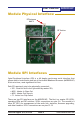
MOD090-HP
User’s Manual
Module UART Interface
Here are the Signal denitions for the AW900SPI in UART mode:
Pin Number Name Description
1 Vcc 3.3 vdc for MOD090-HP
2 /CS_LED Chip select for external programming device
3 /CS_PD Chip select for LEDs and DIP switches (active low)Chip s
4 SCK0 Serial clock for LEDs and DIP switches
5 MISO0 Data in for LEDs and DIP switches
6 MOSI0 Data out for LEDs and DIP switches
7 GND MOD090-HP Ground
8 NC Not Used
9 NC Not Used
10 NC Not Used
11 NC Not Used
12 NC Not Used
13 NC Not Used
14 MOSI1 UART TX
15 MISO1 UART RX
16 RFVcc 3.3 vdc for RF section
17 RFGND RF section ground
In UART mode, the MOD090-HP's command interface is moved to SPI0. The LEDs and
DIP switches may still be employed, but the primary purpose of this SPI port has
shifted. SPI1 now becomes an asynchronous UART with TX on pin 14 and RX on pin
15 and is used for data that is transmitted and received via the RF.
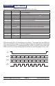
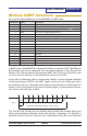
At the risk of belaboring what is obvious and familiar to most engineers because
of the long history of RS-232, the UART signals consist of a set of bits sent with a
pre-dened clock rate. The sender must agree on what the rate is, and because the
sender’s clock and receiver’s clock may not exactly agree, synchronization informa-
tion is sent with each byte of data:
Start
Bit
D
0
D
1
D
2
D
3
D
4
D
5
D
6
D
7
Stop
Bit
T
Baud Rate = 1/T
Single byte transmission (8 bits + Start + Stop)
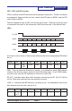
The Stop Bit can actually be any duration and provides the variable delay that
allows synchronization between sender and receiver. Sometimes, the Stop Bit is
specied to be at least two intervals. Also, sometimes a Parity Bit is sent between
t
0
t
1
t
2
t
3
t
4
t
5
t
6
t
7
t
8
t
9
t
10
Mark
Space