
User's Manual
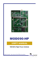
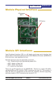

MOD090-HP
User’s Manual
PAGE 6
Technical support (650) 384-0000 www.avalanwireless.com
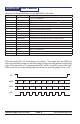
Here are the Signal denitions for the AW900SPI in SPI mode:
Pin Number Name Description
1 Vcc 3.3 vdc for MOD090-HP
2 /CS_LED Chip select for LEDs and DIP switches (active low)C
3 /CS_PD Chip select for external programming devicehip s
4 SCK0 Serial clock for LEDs and DIP switches
5 MISO0 Data in for LEDs and DIP switches
6 MOSI0 Data out for LEDs and DIP switches
7 GND MOD090-HP Ground
8 Error Flag 1=last command not understood. Clear with /CS_BB
9 Data Ready 1=data packet available, 0=no data
10 FIFO Full Flag 1=FIFO full, don’t send any more data, 0=FIFO is empty
11 Connected Flag 1=RF connection present, 0=RF searching/standby
12 /CS_BB Chip select for MOD090-HP
13 SCK1 Serial clock for MOD090-HP
14 MOSI1 Data out for MOD090-HP
15 MISO1 Data in for MOD090-HP
16 RFVcc 3.3 vdc for RF section
17 RFGND RF section ground
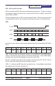
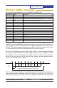
SPI0 uses mode (0,0) for clock phase and polarity. This means that the SCK0 line
idles low and data is setup on the falling edge of the clock and latched on the rising
edge. SPI1 uses mode (1,1), meaning that SCK1, MISO1 and MOSI1 are all idle high.
Data is still set up on the falling edge and latched on the rising edge of the clock.
CS
MISO b7 b6 b5 b4 b3 b2 b1 b0
MOSI b7 b6 b5 b4 b3 b2 b1 b0
SCK