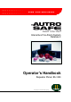
Interactive Fire Alarm System Release 3 Operator's Handbook Repeater Panel, BU-320 Protecting life, environment and property... ASAFE-FB/FE Rev.
COPYRIGHT © This publication, or parts thereof, may not be reproduced in any form, by any method, for any purpose. Autronica Fire and Security AS and its subsidaries assume no reponsibility for any errors that may appear in the publication, or for damages arising from the information in it. No information in this publication should be regarded as a warranty made by Autronica Fire and Security. The information in this publication may be updated without notice.
Table of Contents Table of Contents 1. Introduction ..................................................................... 3 1.1 1.2 1.3 1.4 About the Manual...............................................................................3 The Reader ........................................................................................3 Reference Documentation .................................................................3 Components ......................................................................
Table of Contents 7. Appendix.......................................................................... 22 7.1 8. Index Terms and Abbreviations...................................................................22 .......................................................................... 24 9. Figure List ....................................................................... 25 10. Reader’s Comments .......................................................
Introduction 1. Introduction 1.1 About the Manual This manual is intended to provide the information necessary to operate the AutroSafe Interactive Fire Alarm System from the Repeater Panel, BU-320. 1.2 The Reader The handbook is intended to be used by the fire brigade and personnel who are responsible for operating the system.
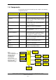
1.4 Components The AutroSafe Interactive Fire Alarm System comprises the following components (EN-54) : Component Abbreviation Point Description - Control and indicating equipment c.i.e. Power Supply - Ref. Detector or manual call-point. A/ D Equipment supplying power to, as well as accepting fault and alarm signals from detectors. Indicates an alarm condition audibly and visibly, plus the location.
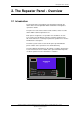
The Repeater Panel - Overview 2. The Repeater Panel - Overview 2.1 Introduction The Repeater Panel is intended to give information related to fire alarms in the relevant Operation Zone and allow the fire brigade to operate fire alarms. The panel is used to silence and resound sounders, and to reset fire alarms within a defined operation zone. Each panel is assigned to one operation zone. Relative to its own zone, a panel is local while it is remote to all other operation zones.
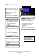
The Repeater Panel - Overview 2.2 Indication Devices Text Display - See chapter 2.3. ALARM The red alarm indicator shows that one or more detection zones within the operating zone of the Repeater Panel are in the fire alarm state. ALARM AUTROSAFE SelfVerify • Blinking red light: In the event of a fire alarm. The Fire Alarm Devices (FAD) are still in active state. Fault Function Disabled Mute Panel Function Delayed • Steady red light: Fire Brig.
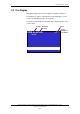
The Repeater Panel - Overview 2.3 The Display During Normal Operation, the back light in the display is always on. The display has 16 lines of 40 characters and is divided into several sections showing different types of information. The picture below shows the information that is displayed in the event of a fire alarm.
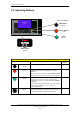
The Repeater Panel - Overview 2.4 Operating Buttons Front Push Buttons ALARM AUTROSAFE Mute Panel (black) SelfVerify Fault Function Disabled Mute Panel Function Delayed Fire Brig. Signalled Silence Alarms (red) Silence Alarms More Events Reset Power Reset (green) More Events v More Events (black) Front Push Buttons Button Mute Panel (black) Silence Alarms (red) Designation Access Level Used to mute the panel. Timeout.
The Repeater Panel - Overview 2.5 Internal Buzzer Each Repeater Panel provides a buzzer which is activated as described below. Each condition may have its own sound pattern. If more than one condition is present simultaneously, the state of the operator panel and the buzzer signal will be decided. The buzzer will reflect the condition which has the highest priority. The internal buzzer is controlled by hardware.
Operation Mode 3. Operation Mode 3.1 Introduction The Repeater Panel operates in Operation Mode, and will automatically enter this mode after startup The display may look as follows in the panel’s idle state. 19:23 Total: 3 AUTROSAFE SelfVerify Figure 3-1: The idle display 3.2 Conditions in Operation Mode In Operation Mode, the system can be in quiescent condition (lowest priority), or in one or any combination of several conditions.
Operation Mode 3.3 Alarm Levels A detector may signal different levels of alarm, indicating the amount of smoke or gas currently present. These are; • Fire Alarm Level (the highest level) • Fire Warning, including: - Prealarm Level - (the lowest level Early Warning is not yet implemented) Note that only the Fire Alarm Level is indicated on the Repeater Panel BU-320.
Operation Mode 3.5 How Fire Alarms are Presented in the Display Fire alarms are presented in Operation Mode. FIRE ALARMS is shown in the upper left corner of the display. The example below shows a situation where three zones are in alarm state. The total number of zones in alarm is shown in the upper right corner.
Operation Mode 3.6 Resounding the Internal Buzzer After pressing the MUTE PANEL button in an alarm condition, the internal buzzer will automatically be resounded in the following cases: • if any new fire alarms occur (for example, if a detection zone enters the Fire Alarm state) • after a timeout period if the cause for making it sound is still present. 3.
Operation Mode 3.9 Alarm Disablement (AlarmDisable) If there are points within an operation zone still signalling a Fire Alarm after the reset button has been pressed, an alarm disablement will take effect. Alarmdisabling may or may not be required to be confirmed by the operator (configurable). • If confirmation is not required, all points still signalling a Fire Alarm, are automatically disabled. • If confirmation is required, a list of points in alarm is presented on the display.
About «In the Event of….» 4. About «In the Event of….» The subsequent chapters - In the event of deal with different events that may occur; Chapter In the event of…..
In the Event of a Fire Alarm 5. In the Event of a Fire Alarm 5.1 Indications in the Event of a Fire Alarm One or several fire detectors or manual call points in one or several detection zones are signalling a Fire Alarm. The following shows the indications on the Repeater Panel in the event of «Fire Alarm» within the operation zone of the panel. The text display indicates the detection zones in alarm state and their location. The red Alarm indicator is blinking.
In the Event of a Fire Alarm 5.2 Actions to be Taken in the Event of a Fire Alarm Step Actions to be taken 1 Follow all precautions described in the local fire instructions, step by step. Display Indication FIRE ALARMS Audible Indication 19:23 Total: 3 1 OFFICES 2 CANTEEN 3 WORKSHOP All fire alarm devices connected to the alarm zones (which are connected to the detection zones in alarm) are activated (sounders and visual indicators). The internal buzzer on the Repeater Panel is turned on.
In the Event of a Fire Alarm Step Actions to be taken Display Indication Audible Indication By means of the SILENCE button, you can manually resound the alarm zones at this stage. 5 Press the green Reset button. Info Comments: 19:23 Total: 19:23 3 RESET The audible indicator on all panels within the operation zone of the Repeater Panel is turned off. : Completed If there are no points signalling a fire alarm, the system is reset. The red FIRE indicator goes off. The red Fire Brig.
In the Event of a Fire Alarm with Alarm Delay In the Event of a Fire Alarm with Alarm Delay 5.3 Indications - Fire Alarm with Alarm Delay A point set to Delayed Action (configurable) is sending an alarm signal from a Delayed Action detection zone in a situation where Immediate Output Actioning has been disabled, i.e. the alarm delay has been activated.
In the Event of a Fire Alarm with Alarm Delay 5.4 Actions to be Taken - Fire Alarm with Alarm Delay Step Actions to be taken 1 Follow all precautions described in the local fire instructions, step by step. Comments: Display Indication Audible Indication 19:23 Total: 1 FIRE ALARMS 1* KITCHEN FIRST DELAYED OUTPUTS ACTIVATES 19:30 The internal buzzer on the Repeater Panel is turned on. The red FIRE indicator starts to blink.
In the Event of a Fire Alarm with Alarm Delay Step Actions to be taken 5b To silence all alarms, press the red Silence Alarms button. Display Indication 19:23 Total: 19:23 3 SILENCE Info: Audible Indication All Fire Alarm Devices (FAD) are deactivated. Completed FIRE ALARMS 1 KITCHEN Total: 1 FIRE ALARMS 19:23 Total: 1 1 KITCHEN Comments: The red FIRE indicator goes steady.
Appendix 6. Appendix 6.1 Terms and Abbreviations Term / Abbreviation Explanation Activation To bring a component into (one of) its active activation states (depending on type, a component may have several active activation states). Examples of activation are turning a fire extinguisher on and making a sounder to issue a EVACUATE or ALERT signal. Components may be activated and deactivated either on command or on alarm.
Appendix Term / Abbreviation Explanation Fire Alarm Routing Equipment (FARE) Intermediate equipment which routes an alarm signal from control and indicating equipment to a Fire Alarm Receiving Station. Fire Detector The part of an automatic fire detection system which constantly or at frequent intervals monitors suitable physical and/or chemical phenomena for detection of fires in the area under surveillance. Fire Protection Equipment (FPE) Fire control or fighting equipment, e.g.
Index 7. Index access levels, 11 automatic disablement, 14 buzzer, 9 components, 4 conditions, 10 Fire Alarm, 16 Fire Alarm with Alarm Delay, 20 Front Push Buttons, 8 In the event of…..-, 15 levels of alarm, 11 Mute Panel, 8 Operation Mode, 10 RESET button, 13 Reset System, 8 Silence Alarms, 8 Operator's Handbook, AutroSafe Interactive Fire Alarm System, Release 3, ASAFE-FB/FE Rev.
Figure List 8. Figure List Figure 3-1: The idle display........................................................................10 Figure 3-2: How fire alarms are presented ..............................................12 Operator's Handbook, AutroSafe Interactive Fire Alarm System, Release 3, ASAFE-FB/FE Rev.
Operator's Handbook, AutroSafe Interactive Fire Alarm System, Release 3, ASAFE-FB/FE Rev.
Reader’s Comments 9. Reader’s Comments Please help us to improve the quality of our documentation by returning your comments on this manual: Title: Operator's Handbook, Repeater Panel, BU-320 AutroSafe Interactive Fire Alarm System, Release 3, Ref. No.: ASAFE-FB/FE Rev. A, 010531 Your information on any inaccuracies or omissions (with page reference): Please turn the page Operator's Handbook, AutroSafe Interactive Fire Alarm System, Release 3, ASAFE-FB/FE Rev.
Reader’s Comments Suggestions for improvements Thank you! We will investigate your comments promptly.
Autronica Fire and Security AS is an international company, based in Trondheim, Norway and has a world-wide sales and service network. For more than 40 years Autronica’s monitoring systems have been saving lives and preventing catastrophes on land and at sea. Autronica Fire and Security’s most important business area is fire detection & security. Autronica Fire and Security stands for preservation of environment, life and property.