
User guide

Upgrading System Software
Commissioning Handbook, AutroSafe Interactive Fire Alarm System, Release 3, P-ASAFE/EE Rev. E, 2005-02-16,
Autronica Fire and Security AS
Page 35
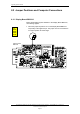
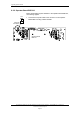
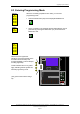
• Connect a computer to the connector X22 on the Display Board
(BSR-310) board.
At the computer side the cable is connected to one of the serial
ports.
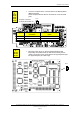
• Move the jumper at JP1 on the Processor Board EAC-300
temporarily one position down (so that the two lowest pins are
used). The jumper is to be moved back to its original position (the
two uppermost pins) at a later stage.
Computer Connection
on Display Board BSR-310
Signal 9 Pins Computer
Connector
3 Pins BSR-310 Connector
(X22)
RX 2 3
TX 3 2
0V 5 1
1 2 3
Applies
to
BS-310
BS-320
BS-330
BV-320
BU-320
Applies
to
BS-310
BS-320
BC-320
JP1