
User guide

Commissioning Handbook, AutroSafe Interactive Fire Alarm System, Release 3, P-ASAFE/EE Rev. E, 2005-02-16,
Autronica Fire and Security AS
Page 15
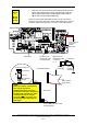
4.1.6 Verification Procedure for Fire Alarm Control Panel / Controller
Consult if necessary the relevant drawings and perform the steps:
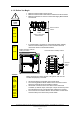
1
Verify that the ribbon cable from the front panel to the Connection Module (BSF-
310B) in the cabinet is fitted.
2
Verify that the ribbon cable from Connection Module (BSF-310B) to Communication
Module (BSL-310) is fitted.
3
Verify that the ribbon cable from Communication Module (BSL-310) to the Power
Supply (BSS-103A/02) is fitted.
4
Verify that the earth strap solded to the upper right corner of the Power Supply to
the Protective Earth to cabinet connection (right side wall, upper attachment of front
panel) is connected.
5
Verify that the strap from the Protective Earth to cabinet connection to the Chassis
connection is connected.
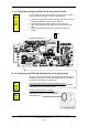
6
Verify that the resistance between 0v to Protective Earth is >50k ohm. Measure
between connection X5 to X1 on the Power Supply (BSS-103A/02).
7
If batteries are installed internally or in a separate cabinet, disconnect the batteries
electrically by disconnecting battery wires (remove connector X3 on BSF-310B).
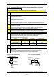
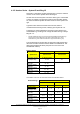
8
Verify that the 24V polarity is kept correct between Power Supply (BSS-103A/02),
Connection Module (BSF-310B) and the internal Power I/O Module (BSS-310).
Correct connection is verified by means of the measuring instrument.
Verify the connected circuits point-to-point:
Signal Power Supply
BSS-103A/02
Connection
Module BSF-310B
Internal Power
I/O Module BSS-310
+24V (Battery) X4 X1.1 Pin 1
0V (Battery) X5 X1.2 Pin 3
Protective Earth /
Chassis
X1 X1.3 Pin 5
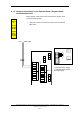
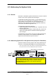
9
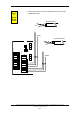
Verify the external connections from the AUTROLON to the Connection Module
BSF-310B.
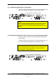
10
Verify the internal AUTROLON connections between the Connection Module BSF-
310B and the;
Fire Alarm Control Panel's Display Board BSR-310 (see previous page and/or
the Controller's LON Interface Board EAU-310 (see drawing below).
BSF-310B board
Connector
Wires pointing
downwards
4-pin terminal
4-pin
terminal
EAU-310
board
Connector
Wires
pointing
inwards
Applies to BS-320 and BC-320
Top view: BSF-310B board
Side view: EAU-310 board