
User guide

Commissioning Handbook, AutroSafe Interactive Fire Alarm System, Release 3, P-ASAFE/EE Rev. E, 2005-02-16,
Autronica Fire and Security AS
Page 14
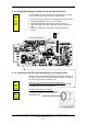
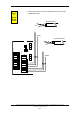
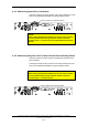
3. Verify the connections of the internal AUTROLON cable and the
ribbon cable between the Connection Module BSF-310B and;
(A) the Display Board BSR-310 (BS-330/BU-320/BV-320) or
(B) the EAU-310 Board (BS-320/BC-320).
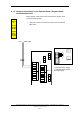
NOTE: On the Operator Panel BS-330, there are two connectors
inside the front panel door for the ribbon cable. Make sure to connect
the ribbon cable to the uppermost connector on the Display Board.
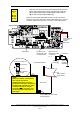
Connection Module
4-pin
terminal
EAU-310
board
Connector
Wires
pointing
inwards
circuit board
Connector
Wires pointing
upwards
4-pin terminal
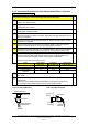
Chassis
0V
+24V
0V
+24V
0V
+24V
-
+
SHIELD
X1-4
Ribbon Cable to
Connection
Module
BSF-310B
(A) Terminal for
A
UTROLON Cable
on Display Board
Ribbon cable to
Display Board
Terminal for AUTROLON Cable
(to Display Board)
Display Board
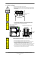
NOTE:
Make sure that the connectors on
each side of the internal
AUTROLON cable are correctly
positioned on the 4-pin terminal (on
the BSF-310B and BSR-310 / EAU-
310 board). All
4 pins must be
connected to the connector, and
the wires must point upwards on
both sides.
(B) Terminal for
A
UTROLON Cable
on EAU-310
Bd
Applies
to
BS-330
BV-320
BU-320
BSF-310B
BSR-310
Reset button