
User guide

Commissioning Handbook, AutroSafe Interactive Fire Alarm System, Release 3, P-ASAFE/EE Rev. E, 2005-02-16,
Autronica Fire and Security AS
Page 12
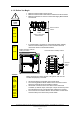
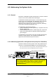
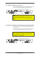
4.1.5 Verifying Connections on the Operator Panel / Repeater Panel
and Information Panel
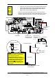
Before startup, make sure that all connections are properly done.
Verify the following steps:
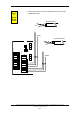
1. Verify the connections to 24V DC to the Connection Module
BSF-310B.
E
X
T
2
4
V
0V
+24V
0V
+24V
0V
+24V
0V
+24V
24V Source
24V Source
F3
0V
+24V
0V
+24V
LON B
LON B
SHIELD
LON A
LON A
SHIELD
F1
Chassis
0V
+24V
0V
+24V
0V
+24V
-
+
SHIELD
F
AU
L
T
O
U
T
P
.
B
A
T
T
I
O
C
H
A
R
G
E
X
1
-
4
X
5
-
7
E
X
T
2
4
V
L
O
N
F4
F
2
,
0
A
T
3
,
1
5
A
If redundant power supply
is available, these external
24V inputs apply.
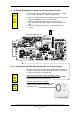
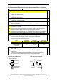
Applies
to
BS-330
BV-320
BU-320
(applies
also to
BS-320
BC-320)
+24V
_
Power input