
User guide

Commissioning Handbook, AutroSafe Interactive Fire Alarm System, Release 3, P-ASAFE/EE Rev. E, 2005-02-16,
Autronica Fire and Security AS
Page 11
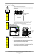
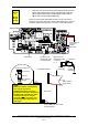
4.1.3 Required Strapping for System Units with Optional Printer
To ensure that the printer functions after commissioning for system
units provided with a printer, be aware of the following:
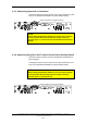
• Before Power ON, make sure that the strap (position X21) on the
Display Board BSR-310 is in its correct position.
• Before downloading (at a later stage), remove the strap.
• After downloading (at a later stage), the power must be turned
OFF.
• Before Power ON (at a later stage), reinsert the strap in its
position.
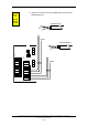
Display Board BSR-310
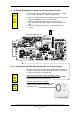
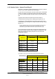
4.1.4 Verifying the AUTROLON Flash Memory on all System Units
All system units are provided with Flash Memory (Flash devices). At
this stage it is important to verify that the Flash devices are inserted
into the correct sockets in all system units.
Operator Panel, Information Panel and Repeater Panel:
The single Flash device is inserted into socket D30 on the Display
Board BSR-310 (refer to drawing above).
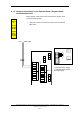
Fire Alarm Control Panel / Controller:
The two Flash devices are inserted into their
sockets D32 and D52 on the LON Interface
Board (EAU-310).
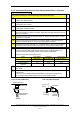
Strap
Applies
to
BS-310
BS-320
BS-330
Applies
to
BS-330
BV-320
BU-320
Applies
to
BS-320
BC-320