Interactive Fire Alarm System Release 3 Commissioning Handbook Protecting life, environment and property... P-ASAFE/EE Rev.
COPYRIGHT © This publication, or parts thereof, may not be reproduced in any form, by any method, for any purpose. Autronica Fire and Security AS and its subsidaries assume no reponsibility for any errors that may appear in the publication, or for damages arising from the information in it. No information in this publication should be regarded as a warranty made by Autronica Fire and Security. The information in this publication may be updated without notice.
Table of Contents Table of Contents 1. Introduction.......................................................................4 1.1 1.2 1.3 About the Handbook ......................................................................... 4 The Reader ....................................................................................... 4 Reference Documentation ................................................................ 4 2. Verifying the Loops ..........................................................5 2.
Table of Contents 4.3.8 If the Configuration Data Must be Reconfigured .................... 28 5. Entering Required Access Levels ...................................29 6. Verifying System After Download ...................................31 7. Troubleshooting................................................................32 7.1 Distributed System ............................................................................ 32 7.1.1 AUTROLON Service Diode Status After Reset ...................... 32 8.
Table of Contents Commissioning Handbook, AutroSafe Interactive Fire Alarm System, Release 3, P-ASAFE/EE Rev.
Introduction 1. Introduction Important – removing/changing Loop Units If it is necessary to remove/change loop units for any reason during normal operation, never remove more than one loop unit at the time. 1.1 About the Handbook This handbook is intended to provide all necessary information for the commissioning of the AutroSafe Interactive Fire Alarm System.
Verifying the Loops 2. Verifying the Loops 2.1 AS-2000 Loop Diagnostic Tool All loops should be verified with the AS-2000 Loop Diagnostic Tool before startup. Although this is presumably already done at an earlier stage (shortly after the installation), it is recommended that all loops are verified once again in case minor changes have been done. By doing this, you will eliminate possible problems during the startup procedure and downloading of configuration data.
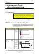
Consistency Check of Configuration Data 3. Consistency Check of Configuration Data 3.1 Introduction NOTE: To ensure a problem-free download of configuration data, always perform a consistency check, using the results from the AS-2000 verification and the data that has been configured by means of the AutroSafe Configuration Tool. 3.2 Parameters Used for the Consistency Check The table below provides a description of two of the parameters that are used for the consistency check.
3.3 Importing Loop Data from the AS-2000 Tool The AutroSafe Configuration Tool features an Import command allowing you to import loop data directly from the AS-2000 Loop Diagnostic tool. In this way, it is possible to ensure that the point types and sequence indexes in the configuration will be identical to the real loop. Tag Names and optional Detection Zones (DZs) will be assigned to the points during import.
4. Commissioning Procedure This chapter covers the commissioning of both a standalaone system and a distributed system with several system units operating on the local operating network; AUTROLON.
4.1 Verifying the System Before Startup 4.1.1 Recommended Equipment When performing the verification procedure, we recommend that a high-ohmic universal measuring instrument is used. The internal resistance should be approximately 5 Mohm. Commissioning Handbook, AutroSafe Interactive Fire Alarm System, Release 3, P-ASAFE/EE Rev.
4.1.2 Before You Begin ! • Make sure that the mains power is OFF. • Make sure that the mains inlet and the batteries are disconnected. • Make sure that fuse F1 and F2 on the Power Supply BSS-103A/02 are removed. Mains Power OFF! Applies to BS-320 BC-320 Applies to SY-310 F3 F2 Remove fuse F1 and F2.
4.1.3 Required Strapping for System Units with Optional Printer Applies to BS-310 BS-320 BS-330 To ensure that the printer functions after commissioning for system units provided with a printer, be aware of the following: • Before Power ON, make sure that the strap (position X21) on the Display Board BSR-310 is in its correct position. • Before downloading (at a later stage), remove the strap. • After downloading (at a later stage), the power must be turned OFF.
4.1.5 Verifying Connections on the Operator Panel / Repeater Panel and Information Panel Before startup, make sure that all connections are properly done. Verify the following steps: Applies to 1. Verify the connections to 24V DC to the Connection Module BSF-310B.
2. Verify the connections from the AUTROLON to the Connection Module BSF-310B. Applies to BS-330 BV-320 BU-320 AUTROLON IN Shield +_ Shield F2,0A F0,63A AUTROLON OUT Shield F3 SHIELD +24V LON B LON B SHIELD LON A LON A T2,5A BATT + +24V 0V EXT 24V IO 0V +24V 0V Shield F2 LON 0V +24V FAULT OUTP. 0V +24V +_ X5-7 Chassis CHARGE X1-4 F4 SHIELD Commissioning Handbook, AutroSafe Interactive Fire Alarm System, Release 3, P-ASAFE/EE Rev.
3. Applies to BS-330 BV-320 BU-320 Verify the connections of the internal AUTROLON cable and the ribbon cable between the Connection Module BSF-310B and; (A) the Display Board BSR-310 (BS-330/BU-320/BV-320) or (B) the EAU-310 Board (BS-320/BC-320). NOTE: On the Operator Panel BS-330, there are two connectors inside the front panel door for the ribbon cable. Make sure to connect the ribbon cable to the uppermost connector on the Display Board.
4.1.6 Verification Procedure for Fire Alarm Control Panel / Controller Applies to BS-320 and BC-320 Consult if necessary the relevant drawings and perform the steps: 1 Verify that the ribbon cable from the front panel to the Connection Module (BSF310B) in the cabinet is fitted. 2 Verify that the ribbon cable from Connection Module (BSF-310B) to Communication Module (BSL-310) is fitted. 3 Verify that the ribbon cable from Communication Module (BSL-310) to the Power Supply (BSS-103A/02) is fitted.
4.2 Addressing the System Units 4.2.1 General Note that in a standalone system where BS-310 is used, the switches must be set to 0 for the System ID and the Ring ID. A distributed AutroSafe system requires a correct addressing of all system units on the AUTROLON. The addressing, which is set with rotary switches on each system unit, must correspond to the addressing that is defined for the specific configuration (defined by means of the AutroSafe Configuration Tool).
4.2.3 Addressing System ID on Controllers System ID numbers are set by means of two rotary switches (S17 and S16) on the Operator Board BSZ-310 (see illustration below). Rotary switches on the Operator Board NOTE! When setting hexadecimal numbers on the two rotary switches on the Operator Board, always read the numbers from left towards right, i.e. from S17 to S16 (except addresses 02=S17=0, S16=2). 4.2.
4.2.5 Number Series - System ID and Ring ID Note that in a standalone system where BS-310 is used, the switches must be set to 0 for the System ID and the Ring ID. As there can be several system units of the same type in a distributed system, for example, two Operator Panels, three Information Panels etc, there are defined System ID number series for each System Unit type. A general rule is that the Fire Alarm Control Panel, which is considered as the Booting Panel, is always given System ID = 01.
4.2.6 Examples of Addressing Example 1: A Fire Alarm Control Panel is to be given System ID = 01. The correct hexadecimal numbering on the rotary switches on the Display Board BSR-310 is shown on the drawing below. S102 S101 1 0 Read from left towards right Example 2: The Fire Alarm Control Panel is to be given Ring ID = 01 The correct hexadecimal numbering on the rotary switches on the Operator Board BSZ-310 is shown on the drawing below.
4.2.7 Jumper Settings on the LON Interface Board The Fire Alarm Control Panel and the Controller are both provided with the necessary LON Interface Board (EAU-310). The board must have the correct jumper settings (factory set). This is done by setting jumpers in the correct positions on the connector located at the right bottom side of the LON Interface Board (see drawing below). The LON Interface Board is shown as it is mounted onto the Processor Board EAC-300 in the Fire Alarm Control Panel or Controller.
4.3 Startup Procedure 4.3.1 Preparing the Fire Alarm Control Panel / Controller 1 2 3 4 Connect the mains inlet on the Power Supply (BSS-103/02) to the external source. 5 Applies to the Fire Alarm Control Panel. Connect a computer to the connector X22 on the Display Board (BSR-310) board. Measure the voltage (230V) across X2-X3 on the Power Supply (BSS-103/02). Check that you have the correct addressing according to the configuration data.
4.3.2 Entering Programming Mode When the necessary preparations are made, you can enter programming mode. This is done by pressing the reset button on the Display Board BSR-310. As the Controller is not equipped with the Display Board, reset is performed by pressing the reset button on the Processor Board EAC-300.
4.3.3 Configuration Files The AutroSafe Configuration Tool generates the following configuration files: System Unit Configuration Files (binary) Fire Alarm Control Panel BS-320 BsrFlash.bin EacEeprom.bin EacFlash.bin Controller BC-320 EacEeprom.bin EacFlash.bin Operator Panel BS-330 BsrFlash.bin Repeater Panel BU-320 BsrFlash.bin Information Panel BV-320 BsrFlash.
4.3.4 Communication Setup • Double-click the AutroSafe Download Tool icon and the communication setup menu will appear on screen. • Select the communication port that is used. • Click OK. 4.3.5 Locating Configuration Files • The configuration files are automatically sorted in different folders in the Installation/Config_Bin directory. Refer to chapter 4.3.3. • Use the browser to locate the configuration files for the Display Board BSR-310 (does not apply to the Controller BC-320).
4.3.6 Downloading Configuration Files • When downloading configuration data to the different system units in a distributed system, make sure to download the configuration files from the correct folders (see previous chapter).
4.3.7 Booting the System from the Fire Alarm Control Panel BS-320 (Booting Panel) The initialization of the system is done from the Fire Alarm Control Panel (the booting panel). Refer to chapter 4.2.4 and 4.2.5. When the downloading procedure is complete and the reset button on the Display Board BSR-310 is pressed, the following will appear on the booting panel's screen (example): 15:10 Starting Paneltype = BSSystem SW =x.x.x Config interface =x.x.
• To view the AUTROLON topology before initializing, press digit 2. 15:14 AUTROLON topology RingId = 1 No 1 2 3 Number of Panels: 3 Paneltype BS-320 BU-320 BS-320 SystemId 01 61 02 1: Initialize AutroSafe • To initialize AutroSafe, press digit 1 (Action Digit) on the alphanumeric keyboard.
4.3.8 If the Configuration Data Must be Reconfigured If the distributed system has been changed in some way, for example, new system units or loop units have been added, the configuration data must be reconfigured according to the changes.
5. Entering Required Access Levels All user interface controls are classified as belonging to one of the four different access levels described below: Access Level Access Remedy Description 1 No key or password required. Accessible by members of the general public. All mandatory indications are visible at access level 1 without prior manual intervention. 2 Access by key. Accessible by persons having a specified responsibility for safety. 3 Password restricted.
Entering Required Access Levels Step 3 Actions to be taken Display Indication To select ACCESS LEVEL 3, press 3. SYSTEM 19:23 ACCESS LEVEL 3 1 ENTER ACCESS LEVEL 3 2 LEAVE ACCESS LEVEL 3 3 SET PASSWORD 4 To enter ACCESS LEVEL 3, press 1. SYSTEM 19:23 ACCESS LEVEL 3/ENTER ACCESS LEVEL 3 Enter password: 5 Enter the password, then press SYSTEM ACCESS LEVEL 3/ENTER ACCESS LEVEL 3 twice.
Verifying System After Download 6. Verifying System After Download To ensure that the system works properly during normal operation, the whole system (control panel, detectors, control functions) should be verified after download. Step Description 1 Test the panel indicator lights and internal buzzer by pushing the Mute button more than 5 seconds.
Troubleshooting 7. Troubleshooting 7.1 Distributed System 7.1.1 AUTROLON Service Diode Status After Reset LON Interface Board EAU-310 Display Board BSR-310 Location of Diode(s) Indication Status Actions to be taken Display Board BSR-310 on BS-320 Steady red light. (V32) Normal indication after reset. - Display Board BSR-310 on BU-320 BV-320 BS-330 Light turned off. (V32) Normal indication after reset.
8. Upgrading System Software 8.1 Overview When upgrading System Software versions, each panel has to be prepared before downloading. Note that new configuration files (generated by the matching version of the AutroSafe Configuration Tool) must be downloaded as well. When performing the upgrading procedure on system units in a distributed system, disregard information in this chapter related to circuit boards which are not integrated parts of the actual system unit.
Upgrading System Software 8.2 Jumper Positions and Computer Connections 8.2.1 Display Board BSR-310 Before downloading System Software to the Display Board BSR-310, the following applies: Applies to BS-320 BS-330 BV-320 BU-320 • Move the jumper at position X17 on the Display Board BSR-310 temporarily to the rightmost pin. The jumper is to be moved back to its original position at a later stage.
Upgrading System Software Applies to BS-310 BS-320 BS-330 BV-320 BU-320 • Connect a computer to the connector X22 on the Display Board (BSR-310) board. At the computer side the cable is connected to one of the serial ports.
Upgrading System Software 8.2.2 Operator Board BSZ-310 Before downloading System Software to the Operator Board BSZ-310, the following applies: 123 • Connect the computer cable to the connector on the Operator Board BSZ-310 using cable XJA-029B. Computer Connection Operator Board BSZ-310 Commissioning Handbook, AutroSafe Interactive Fire Alarm System, Release 3, P-ASAFE/EE Rev.
Upgrading System Software 8.3 Entering Programming Mode Applies to BS-310 BS-320 BS-330 BV-320 BU-320 When the necessary preparations are made, you can enter programming mode. Applies to BC-320 • As the Controller is not equipped with the Display Board, reset is performed by pressing the reset button (X1) on the Processor Board EAC-300. • Press the Reset button (S5) on the Display Board BSR-310.
Upgrading System Software 8.4 Installing the AutroSafe Download Tool The AutroSafe Download Tool is already installed on your service computer and will appear as an icon on screen. 8.5 Startup Procedure 8.5.1 Communication Setup • Double-click the AutroSafe Download Tool icon and the communication setup menu will appear on screen. • Select the communication port that is used. • Click OK. Commissioning Handbook, AutroSafe Interactive Fire Alarm System, Release 3, P-ASAFE/EE Rev.
Upgrading System Software 8.5.2 About System Software Files To upgrade system software, you have to download the system software files to target.
Upgrading System Software 8.5.3 Locating System Software Files • Use the browser to locate the System Software files for the Display Board BSR-310 (does not apply to the Controller BC-320). Click on the search box to search for the opeq_bin file in the dialog box, then press Open. • Use the browser to locate the System Software files for the Processor Board EAC-300 (does not apply to the Operator Panel BS-330, Repeater Panel BU-320 and Information Panel BV-320).
Upgrading System Software 8.5.6 Re-placing the Jumpers When the downloading is completed, the jumpers are to be moved back to their original positions. • Move the jumper back to its original position X17 on the Display Board BSR-310. • Move the jumper at position JP1 back to its original position (the two uppermost pins on the Processor Board EAC-300). JP1 Commissioning Handbook, AutroSafe Interactive Fire Alarm System, Release 3, P-ASAFE/EE Rev.
Upgrading System Software 8.5.7 Rebooting the System When the System Software is downloaded to target, the system unit has to be rebooted. Applies to BS-310 BS-320 BS-330 BV-320 BU-320 Applies to BC-320 • Press the Reset button (S5) on the Display Board BSR-310. • As the Controller is not equipped with the Display Board, reset is performed by pressing the reset button (X1) on the Processor Board EAC-300. Commissioning Handbook, AutroSafe Interactive Fire Alarm System, Release 3, P-ASAFE/EE Rev.
Guidelines When Expanding to Distributed System 9. Guidelines When Expanding to Distributed System If you have a standalone AutroSafe system, you can easily upgrade and expand your system to a distributed system. The following guidelines apply: Step Action To Take Remarks Mount the required LON Interface Board EAU-310 onto the EAC-300 Board inside the Fire Alarm Control Panel BS-310 You will now actually have a BS-320 panel.
Inserting / Feeding Paper for the Optional Printer Inserting / Feeding Paper for the Optional Printer If the Fire Alarm Control Panel (Operator Panel) is equipped with an optional printer, the following must be done: 1. Enter the Printer selection in the System Menu as shown below. Step 1 Actions to be taken Display Indication To enter the Main Menu, press MAIN MENU 19:23 1 SHOW STATUS 2 DISABLE 3 ENABLE 4 SYSTEM 5 SERVICE 6 OUTPUT CONTROL 2 To select SYSTEM, press 4.
Inserting / Feeding Paper for the Optional Printer 2. Open the frontpanel. 3. Make sure that the end of the paper roll has a clean 90o cut. 4. Insert the end of the paper roll - pointing upwards- between the small horizontal metal bracket and the front panel as shown on the drawing below, align the edges of the paper, then slightly move the paper upwards until the paper is fed. Front Panel Paper pointing upwards Metal bracket 5.
Inserting / Feeding Paper for the Optional Printer 6. Finally, position the paper roll onto the cylinder, then fasten the washer and split pin. Paper role Split pin Washer 7. Close the front panel. 8. To return to the Main Menu, press three times. Commissioning Handbook, AutroSafe Interactive Fire Alarm System, Release 3, P-ASAFE/EE Rev.
Reader’s Comments 11. Reader’s Comments Please help us to improve the quality of our documentation by returning your comments on this manual: Title: Commissioning Handbook AutroSafe Interactive Fire Alarm System, Release 3, Ref. No.: P-ASAFE/EE Rev. E, 2005-02-16 Your information on any inaccuracies or omissions (with page reference): Please turn the page Commissioning Handbook, AutroSafe Interactive Fire Alarm System, Release 3, P-ASAFE/EE Rev.
Reader’s Comments Suggestions for improvements Thank you! We will investigate your comments promptly.
Reader’s Comments Commissioning Handbook, AutroSafe Interactive Fire Alarm System, Release 3, P-ASAFE/EE Rev.
Autronica Fire and Security AS is an international company, based in Trondheim, Norway and has a world-wide sales and service network. For more than 40 years Autronica’s monitoring systems have been saving lives and preventing catastrophes on land and at sea. Autronica Fire and Security’s most important business area is fire detection & security. Autronica Fire and Security stands for preservation of environment, life and property.