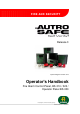
Release 3 System Program Version 3.8.0 Operator's Handbook Fire Alarm Control Panel, BS-310 / 320 / Operator Panel BS-330 Protecting life, environment and property... ASAFE-FO/FE Rev.
COPYRIGHT © This publication, or parts thereof, may not be reproduced in any form, by any method, for any purpose. Autronica Fire and Security AS and its subsidaries assume no reponsibility for any errors that may appear in the publication, or for damages arising from the information in it. No information in this publication should be regarded as a warranty made by Autronica Fire and Security. The information in this publication may be updated without notice.
Table of Contents Table of Contents 1. Introduction.......................................................................5 1.1 1.2 1.3 1.4 About the Handbook ......................................................................... 5 The Reader ....................................................................................... 5 Reference Documentation ................................................................ 5 Components ........................................................................
Table of Contents 3.18.5 Delayed Coincidence Detection Zones................................... 30 3.18.6 Solas Detection Zones............................................................ 31 4. About «In the Event of….» ...............................................32 5. In the Event of a Fire Alarm .............................................34 5.1 5.2 6. In the Event of a Fire Alarm - with Alarm Delay ...........38 6.1 6.2 7. Indications in the Event of a Fire Alarm ................................
Table of Contents 11.5 11.6 11.7 11.8 11.9 11.10 11.11 11.12 Disabling Detection Zones ................................................................ 64 Disabling Points................................................................................. 65 Disabling Fire Alarm Devices ............................................................ 65 Disabling Fire Alarm Routing Equipment .......................................... 65 Disabling Outputs ..........................................................
Table of Contents 14.5.1 Clear Topology........................................................................ 110 14.5.2 Disable Loop ........................................................................... 111 14.5.3 Enable Loop ............................................................................ 112 14.6 Report................................................................................................ 113 14.6.1 SV-Fault ...................................................................
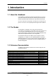
Introduction 1. Introduction 1.1 About the Handbook This handbook is intended to provide the information necessary to operate the AutroSafe Interactive Fire Alarm System from the Fire Alarm Control Panel, BS-310/320 or the Operator Panel, BS-330. As the user interface and operation of both panels are identical, the panel is referred to as the operator panel throughout this handbook. 1.2 The Reader The handbook is intended to be used by personnel who are responsible for operating the system.
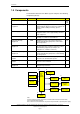
Introduction 1.4 Components The AutroSafe Interactive Fire Alarm System comprises the following components (EN-54) : Component Abbreviation Point - Control and indicating equipment c.i.e. Power Supply - Fire Alarm Devices FAD Fire Alarm Routing Equipment FARE Control for Fire Protection Equipment FPE Fault Warning Routing Equipment FWRE Description Ref. Detector or manual call-point. A/ D Equipment supplying power to, as well as accepting fault and alarm signals from detectors.
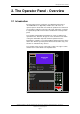
The Operator Panel - Overview 2. The Operator Panel - Overview 2.1 Introduction Each operator panel is assigned to one Operation Zone (refer to «Zonal Definitions» in Appendix). Relative to its own zone, an operator panel is local, while it is remote to operation zones which are not encompassed by the local zone. All events and actions occurring in a particular operation zone must be handled from a local operator panel. The operator panel displays information on events occurring in all operation zones.
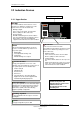
The Operator Panel - Overview 2.2 Indication Devices Text Display - See chapter 2.3. 2.2.1 Upper Section ALARM ALARM The red alarm indicator shows that one or more detection zones within the operating zone of the Operator Panel are in the fire alarm state. • Blinking red light: In the event of a fire alarm. The Fire Alarm Devices (FAD) are still in active state. Fault Function Disabled Fire Brig.
The Operator Panel - Overview 2.2.2 The Operator Section (lower) Testing Fire Brig. Disabled Fire Brig. Fault System Fault Alarms Disabled Alarms Fault 1 2 3 4 5 6 7 8 9 C 0 i ® Testing Steady yellow light when one or more detection zones within the operation zone of the operator panel have been manually set to the test state. Fire Brig. Disabled Steady yellow light when the signal to Fire Alarm Routing Equipment (FARE) has been disabled.
The Operator Panel - Overview 2.3 The Menu Display During Normal Operation, the back light in the menu display is always on. The menu display has 16 lines of 40 characters. The display is divided into several display windows showing different types of information. Header Time SHOW STATUS DISABLEMENTS 1 DETECTION ZONES 2 POINTS 3 FIRE ALARM DEVICES 4 FIRE ALARM ROUTING EQUIPMENT 5 OUTPUTS 6 FAULT WARNING ROUTING EQUIPMENT 7 IMMEDIATE OUTPUT ACTIONING 8 ALL FIRE ALARM 5 CONFERENCE HALL, MAIN BUILDING 19.
The Operator Panel - Overview 2.4 Operating Buttons 2.4.1 Overview Front Push Buttons 19:23 ALARM Mute Panel (black) AUTROSAFE SelfVerify Fault Function Disabled Mute Panel Silence Alarms (red) Function Delayed Fire Brig. Signalled Silence Alarms Reset Power Testing Fire Brig. Disabled Fire Brig.
The Operator Panel - Overview 2.4.2 Front Push Buttons Front Push Buttons Button Designation Mute Panel (black) Silence Alarms (red) Reset (green) v Access Level Used to mute the panel. Timeout. 1 Used to silence Fire Alarm Devices (FAD) and cause blinking serial numbers and lamps to go steady. Timeout. 2 Used to reset the system. 2 In addition, a lamp test can be performed by pressing and holding the Reset button for at least 5 seconds.
The Operator Panel - Overview 2.4.4 Utility Buttons Utility Buttons Button Designation Help The Help button allows you to get useful information quickly while operating the system. You can look up information on how to operate the panel. NOT YET IMPLEMENTED. Menu Used to switch between Operation Mode and Menu Mode. i Operation Mode (operate out) >> Operation Mode.
Operation Mode 3. Operation Mode 3.1 Introduction The operator panel can be in either Operation Mode or Menu Mode. When no one is operating the panel and no button has been pressed, the panel will always be in Operation Mode. The display may look as follows in the panel’s idle state. 19:23 Total: 3 AUTROSAFE SelfVerify Figure 3-1: The idle display Note that an alarm, a disablement, test or fault will always be indicated on the display when such events occur.
Operation Mode 3.2 Conditions in Operation Mode In Operation Mode, the system can be in quiescent condition (lowest priority), or the system can be in one or any combination of the following conditions: • • • • • fire alarm condition (highest priority) fire warning condition (including prealarm and early warning) fault warning condition disablement condition test condition 3.3 Alarm Levels A detector may signal different levels of alarm, indicating the amount of smoke or gas currently present.
Operation Mode 3.5 Configurable Alarm Presentations The alarm presentation is configurable. By default alarms are presented with both zonal indication (detection zones) and point indication. An option is zonal indication only, with the possibility to view point information by operating a button (Action Digit 1: Show Points). Chapter 3.6 deals with the default presentation of alarms. Chapter 3.7 and 3.8 deals with the optional alarm presentation (zonal indication).
Operation Mode 3.6 Alarm Presentation with Zonal and Point Indication (default) By default alarms are presented with both zonal indication and point indication. “FIRE ALARMS” is highlighted in the upper left corner of the display. In the example below an optical smoke detector in the “Main building Show room gr. floor” (1 zone) issues an alarm signal. FIRE ALARMS 19:23 Total: 1 1 Main building Show room gr. floor A1021 Smoke Latest zone in alarm Main building Show room gr.
Operation Mode 3.7 Alarm Presentation with Zonal Indication (optional) Note that the optional alarm presentation with zonal indication is used throughout the handbook. FIRE ALARMS, for example, is shown highlighted in the upper left corner of the display. The example below shows a situation where three zones are in alarm state. The total number of zones in alarm is shown in the upper right corner.
Operation Mode 3.8 How to View Point Information Note that the optional alarm presentation with zonal indication is used throughout the handbook. The default alarm presentation provides both zonal and point information. To be able to select among detection zones in alarm, for example, «In the Event of a Fire Alarm», you simply press the ENTER button ( ). You can now use the up/down arrow buttons to select the wanted zone.
Operation Mode 3.9 How to View Detailed Zonal Information Note that the optional alarm presentation with zonal indication is used throughout the handbook. The default alarm presentation provides both zonal and point information. To be able to select among zones in alarm, fault or test state, you simply press the ENTER button ( ). You can now use the up/down arrow buttons to select the wanted zone (in this example Fire Alarms).
Operation Mode 3.10 Action Digits in Operation Mode When operating in Operation Mode, special Action Digits will appear in the highlighted field (Information Field) at the lower part of the display. These digits show at any time which action the operator may perform. Digits 1 to 4 on the alphanumeric keyboard are dedicated for the different actions (Action Digits). The type of action depends on the current state of the system.
Operation Mode 3.11 Resounding the Internal Buzzer After pressing the MUTE PANEL button in an alarm condition, the internal buzzer will automatically be resounded in the following cases: • if any new event occurs (for example, a detection zone enters the Fire Alarm state) • after a timeout period if the cause for making it sound is still present. 3.
Operation Mode 3.14 Alarm Disablement (AlarmDisable) If there are points within an operation zone still signalling a Fire Alarm, an alarm disablement will take effect. Alarmdisabling may or may not be required to be confirmed by the operator (configurable). • If confirmation is not required, all points still signalling a Fire Alarm, are automatically disabled. • If confirmation is required, a list of points in alarm is presented on the display.
Operation Mode 3.16.2 Point Disablements A general rule is that a Point may be disabled by one or more disablement sources simultaneously. To be enabled, the Point must be enabled from all these disablement sources. Example: A Point is disabled from a Zone (Detection Zone disable command issued from an Operator Panel) and from a Disable Input Unit. For the Point to become enabled, a DZ enable command must be issued from the Operator Panel and the Restore button on the Disable Input Unit must be pressed.
Operation Mode 3.17 Alarm Handling - A Typical Situation The handling of a fire situation will typically contain the following phases: • One or more detection zones are issuing Prealarm signals (Accept). • One or more of these detection zones will go into Fire Alarm, activating Fire Alarm Devices (FAD) and Fire Protection Equipment (FPE).
Operation Mode 3.18 Different Types of Detection Zones 3.18.1 Introduction When handling events in Operation Mode, it is important to be aware of differences regarding the detection zone configuration (configured by using the AutroSafe Configuration Tool). The type of the specific detection zone as well as the type of point (detector or manual call point) will determine how the system responds to the signal - with respect to action.
Operation Mode 3.18.3 Coincidence Action Detection Zones A fire alarm signal from a single detector in a Coincidence Action detection zone, will initiate no actions, i.e. there will be no actioning of outputs to; • Fire Alarm Devices (FAD) • Fire Alarm Routing Equipment (FARE) • Fire Protection Equipment (FPE) - provided that FAD, FARE and FPE are set to Qualified Action (see next page) At least two detectors in the same detection zone must be in alarm state before actions are initiated.
Operation Mode 3.18.4 Delayed Action Detection Zones When the operator panel receives a fire alarm signal from a point in a Delayed Action detection zone (configurable), the actioning of outputs to Fire Alarm Devices (FAD) and/or Fire Alarm Routing Equipment (FARE) can be delayed.
Operation Mode In the display, a detection zone with its outputs delayed is indicated by a @ in front of the zone text. The time for the first delayed action is also displayed. Note that the optional alarm presentation with zonal indication is used throughout the handbook. Delayed Action Indication (@) 19:23 Total: 3 FIRE ALARMS 1 OFFICES 2 CANTEEN 3 @ WORKSHOP FIRST DELAYED OUTPUTS ACTIVATES 19:40 2: ACTIVATE 4: SHOW SUPPR.
Operation Mode 3.18.5 Delayed Coincidence Detection Zones Detection zones configured as Delayed Coincidence Detection Zones have the following properties: In Day Mode (Immediate Output Actioning is disabled), outputs that are configured to be activated by these detection zones will operate according to their actual configuration, i.e. Silent Alarm, Small Alarm or Large Alarm as follows: When a fire alarm signal from the first detector in alarm is received, the following will occur: 1.
Operation Mode 3.18.6 Solas Detection Zones When the operator panel receives a fire alarm signal from a point in a SOLAS - Safety of Life at Sea - detection zone (configurable), all actions will be initiated after a programmed delay has expired. The (T1) delay period is started when a signal from a point is received. Pressing Action digit 4, which represents BLOCK ALARM, will terminate the delay period and block the alarm for an indefinite period of time.
About «In the Event of….» 4. About «In the Event of….» The subsequent chapters - In the event of…..- deal with different events that may occur; Chapter In the event of….. Chapter 5 a fire alarm Chapter 6 a fire alarm with alarm delay (in a Delayed Action detection zone - immediate output actioning disabled) Chapter 7 a fire warning (prewarning/early warning) Chapter 8 faults The list above covers the most common events.
About «In the Event of….» (This page is left blank intentionally) Operator's Handbook, AutroSafe Interactive Fire Alarm System, Release 3, ASAFE-FO/FE Rev.
In the Event of a Fire Alarm 5. In the Event of a Fire Alarm Note that the optional alarm presentation with zonal indication is used throughout the handbook. 5.1 Indications in the Event of a Fire Alarm One or several fire detectors or manual call points in one or several detection zones are signalling a Fire Alarm. The following shows the indications on the Operator Panel in the event of «Fire Alarm» within the operation zone of the panel.
In the Event of a Fire Alarm 5.2 Actions to be Taken in the Event of a Fire Alarm Step Actions to be taken 1 Follow all precautions described in the local fire instructions, step by step. Display Indication FIRE ALARMS Audible Indication 19:23 Total: 3 1 OFFICES 2 CANTEEN 3 WORKSHOP All fire alarm devices connected to the alarm zones (which are connected to the detection zones in alarm) are activated (sounders and visual indicators). The internal buzzer on the operator panel is turned on.
In the Event of a Fire Alarm Step 9 Actions to be taken To silence all alarms, press the red Silence Alarms button. Display Indication SILENCE Info Audible Indication 19:23 All Fire Alarm Devices (FAD) are deactivated. : Completed FIRE ALARMS 3 WORKSHOP Total: 3 FIRE ALARMS 19:23 Total: 3 1 OFFICES 2 CANTEEN 3 WORKSHOP 1: RESOUND Comments: The red FIRE indicator goes steady. To manually resound the alarm zones at this stage, Action Digit 1 (RESOUND) can be pressed.
In the Event of a Fire Alarm Step Actions to be taken The point(s) still in alarm will be shown on the display. If no actions are taken, the points still signalling alarm will automatically be reactivated after a predefined timeout. If you want to disable the point(s) - for example, a manual call-point -still signalling alarm, go to step 11. The points can also be reactivated (step 12) at any time after the disablement (ALARMDISABLE) has taken place.
In the Event of a Fire Alarm with Alarm Delay 6. In the Event of a Fire Alarm with Alarm Delay Note that the optional alarm presentation with zonal indication is used throughout the handbook. 6.1 Indications - Fire Alarm with Alarm Delay A point set to Delayed Action (configurable) is sending an alarm signal from a Delayed Action detection zone in a situation where Immediate Output Actioning has been disabled, i.e. the alarm delay has been activated.
In the Event of a Fire Alarm with Alarm Delay 6.2 Actions to be Taken - Fire Alarm with Alarm Delay Step Actions to be taken 1 Follow all precautions described in the local fire instructions, step by step. Display Indication 19:23 Total: 1 FIRE ALARMS 1*KITCHEN FIRST DELAYED OUTPUTS ACTIVATES 14:40 2: ACTIVATE Comments: Audible Indication The internal buzzer on the operator panel is turned on. 4: SHOW SUPPR. INFO The red FIRE indicator starts to blink.
In the Event of a Fire Alarm with Alarm Delay Step 8 Actions to be taken To Prolong the delay period, press Display Indication Audible Indication 19:23 Total: 1 FIRE ALARMS 1*KITCHEN DELAYED OUTPUTS ACTIVATES 14:40 for the selected zone, then Action Digit 4 (PROLONG DELAY). 1: SHOW POINTS 2: ACTIVATE 4: PROLONG DELAY DELAY DZ 19:23 19:23 Total: 1 FIRE ALARMS 1*KITCHEN DELAYED OUTPUTS ACTIVATES 14:40 9 10 Investigate the scene(s) and carry out the necessary actions.
In the Event of a Fire Alarm with Alarm Delay Step Actions to be taken 12b To silence all alarms, press the red Silence Alarms button. Display Indication Audible Indication SILENCE Info: 19:23 All Fire Alarm Devices (FAD) are deactivated. Completed FIRE ALARMS 1 KITCHEN Total: 1 FIRE ALARMS 19:23 Total: 1 1 KITCHEN 1: RESOUND 4: SHOW SUPPR. INFO Comments: The red FIRE indicator goes steady. To manually resound the alarm zones at this stage, Action Digit 1 (RESOUND) can be pressed.
In the Event of a Fire Warning 7. In the Event of a Fire Warning Note that the optional alarm presentation with zonal indication is used throughout the handbook. 7.1 Indications in the Event of a Fire Warning A fire detector in one of the detection zones has entered Fire Warning state (Prealarm or Early Warning). The following shows the indications on the Operator Panel in the event of Fire Warning (Prealarm or Early Warning) within the operation zone of the panel.
In the Event of a Fire Warning 7.2 Actions to be Taken in the Event of a Fire Warning Step Actions to be taken 1 Follow all precautions described in the local fire instructions, step by step. FIRE WARNINGS To silence the internal buzzer, press the black Mute Panel button FIRE WARNINGS Press and observe the zone(s) in fire warning state in the display. FIRE WARNINGS 2 3 Comments: 4 5 Investigate the scene and carry out the necessary actions.
In the Event of a Fire Warning Step Actions to be taken 9 To accept the Prealarm, press Action Digit 4 (ACCEPT FIRE WARNING). Display Indication ACCEPT DZ FIRE WARNINGS Audible Indication 19:23 19:23 Total: 1 PREALARMS 2 CANTEEN Comments: In this example, only 1 zone is in Prealarm state. If there are several fire warnings, each one can be accepted in turn. Fire warnings that are accepted, will no longer blink in the display.
In the Event of Faults 8. In the Event of Faults Note that the optional fault presentation with zonal indication is used in this chapter. Faults are presented with point indication as default. 8.1 Indications in the Event of Faults A fault is indicated by one of the components (fire detectors, external equipment or other faults). The following shows the indications on the Operator Panel in the event of Faults within the operation zone of the panel. • Blinking light • Unaccepted fault warnings exist.
In the Event of Faults Actions to be Taken in the Event of Faults Ste p Actions to be taken 1 Notify service/technical personnel. Comments: 2 Press and observe the fault warnings in the display. Comments: Display Indication FAULT WARNINGS DZ FAULTS 1 OFFICES OTHER FAULTS 1 LOOP (2) Audible Indication 19:23 Total: 2 Total: 1 Total: 1 The internal buzzer on the operator panel is turned on. The yellow FAULT indicator starts to blink.
In the Event of Faults Ste p Actions to be taken 6 To view all points in fault warning state within the selected detection zone, press Action Digit 1 (SHOW POINTS). Comments: 7 Select the point to be accepted by scrolling with the arrow buttons (if there are several points in fault warning state), then press Display Indication SHOW STATUS Audible Indication 19:23 FAULTS (points) OFFICES Received: 19:23:50 POINT: P5 P6 P2 In this example, detection zone «OFFICES» is selected.
Menu Mode 9. Menu Mode 9.1 How to Enter Menu Mode ) To enter the Menu Mode from operation mode or the panel’s idle state, the Menu button ( ) must be pressed. The menu has 6 different menu selections, including SHOW STATUS, DISABLE, ENABLE, SYSTEM, SERVICE and OUTPUT CONTROL. NOTE: If an alarm condition occurs when you are in Menu Mode, you have to press the Menu button to re-enter Operation Mode in order to activate the Silence Alarms button and the Reset button. 9.
Menu Mode 9.3 Buttons Used to Operate the Menu The alphanumeric key pad (digits 0 to 9 and arrows), the ENTER button ( ) and the close button ( ) are used to move forward and backwards in the different levels of the menu. The CANCEL button (C) is used to cancel an input character (backspace).
Menu Mode 9.5 How to Operate in Menu Mode All menu selections represent a digit. To enter a menu selection, you simply have to press the corresponding digit. Then you can either; • use the keyboard to enter text into an input field or • press the ENTER button ( ) and use the up/down arrows to move the cursor to the desired selection. 9.
Menu Mode 9.6.1 Using the Keyboard to Enter Text into the Input Field In this example, we are looking for OFFICE, and only one selection starts with an «o». • Press 4 times on the alphanumeric button 5 (which includes the letters mno) to enter an «o». 5 MNO 19:23 DISABLE 1st 2nd= 3rd 4th = DETECTION ZONES o KITCHEN CANTEEN OFFICES WORKSHOP The display will change as soon as the letter «o» is entered. Only selections starting with the letter «o» will be listed (in this example, only OFFICES).
Menu Mode 9.6.2 Using the Up/Down Arrows in the Selection Field In this example, we want to select OFFICES by using the up/down arrows in the selection field. • Press the ENTER button ( ), then use the arrow buttons to move up and down. (In this example the first selection KITCHEN is highlighted and the arrow down button is used to select OFFICES).
Menu Mode (This page is left blank intentionally). Operator's Handbook, AutroSafe Interactive Fire Alarm System, Release 3, ASAFE-FO/FE Rev.
Show Status 10. Show Status 10.1 Introduction The Show Status menu is accessed from the main menu in Menu Mode. The menu gives the current status of the following conditions: • Fire Alarms • Fire Warnings • Faults • Disablements • Detection Zones in test • Activated Outputs 10.
Show Status 10.3 Show Status - Fire Alarms This menu gives detailed information on the current status of fire alarms in the system. It provides the following information: • the location • the exact time of activation • an identification of the detectors (address) • the type of detectors (optical, heat, etc.) • all detectors in alarm • all activated outputs The example below describes how to view the current status of fire alarms.
Show Status 10.4 Show Status – Fire Warnings This menu gives detailed information on the current status of Fire Warnings (Prealarms / Early Warnings) in the system. It provides the following information: • the location • the exact time of activation • an identification of the detectors (address) • the type of detectors (optical, heat, etc.) • all detectors in Fire Warning The example below describes how to view the current status of Fire Warnings.
Show Status 10.5 Show Status - Faults This menu gives detailed information on the current status of faults in the system. It provides the following information: • the location • an identification of the address • the nature of the fault • a detailed text The example below describes how to view the current status of faults.
Show Status 10.6 Show Status - Disablements This menu gives detailed information on the current status of the disablements in the system.
Show Status Step 4 Actions to be taken To select, press the relevant number (1-8).
Show Status 10.7 Show Status - Detection Zones in Test This menu gives detailed information on the zones in test mode. The example below describes how to view the current status of zones in test mode. Step 1 Actions to be taken Display Indication To enter the Main Menu, press MENU 19:23 Total: 3 1 SHOW STATUS 2 DISABLE 3 ENABLE 4 SYSTEM 5 SERVICE 2 To select SHOW STATUS, press 1.
Show Status Show Status – Activated Outputs This menu gives detailed information on activated outputs. The example below describes how to view the current status of activated outputs. Step 1 Actions to be taken Display Indication To enter the Main Menu, press MENU 19:23 Total: 3 1 SHOW STATUS 2 DISABLE 3 ENABLE 4 SYSTEM 5 SERVICE 2 To select SHOW STATUS, press 1.
Show Status Step 4 Actions to be taken To select, press the relevant number (1-8).
Disabling 11. Disabling 11.1 General From the Disable menu you can disable the following: • Detection Zones • Points (fire detectors, manual call points) • Fire Alarm Devices (FAD) • Fire Alarm Routing Equipment (FARE) • Outputs • Fault Warning Routing Equipment (FWRE) • Immediate Output Actioning When disabling components, a disablement time is given. The disablement time can be increased for already disabled components by entering the disable menu.
Disabling 11.3 Indications on the Operator Panel When one or several disablements exist, the Function Disabled indicator on the Operator Panel will show a yellow steady light. The panel’s display will indicate that a disablement exists (as shown in the example below). DISABLEMENTS DISABLED DZs 1 CANTEEN 19:23 Total: 1 Total: 1 Figure 11-2: Disablement - indications on the display 11.
Disabling 11.6 Disabling Points When you disable a Point (fire detectors / manual call-points), no alarm signal or fault signal from this point will be sent in the event of an alarm / fault. A disablement time can be set. When the disablement time expires, the point(s) will automatically be enabled. The point(s) can also be enabled manually from the Enable Menu. If all points in a detection zone are disabled, the detection zone will be indicated as disabled.
Disabling 11.10 Disabling Fault Warning Routing Equipment When you disable Fault Warning Routing Equipment (FWRE), the output which controls such equipment will be disabled. In the event of a fault, no fault warning signals will be sent to, for example, the security firm. A disablement time can be set. When the disablement time expires, the Fault Warning Routing Equipment will automatically be enabled. The equipment can also be enabled manually from the Enable Menu. 11.
Disabling 11.12 How to Execute Commands from the Disable Menu The example below shows how to disable a Detection Zone. The similar procedure applies to all other selections (1-7). Step 1 Actions to be taken Display Indication To enter the Main Menu, press MENU 19:23 Total: 3 1 SHOW STATUS 2 DISABLE 3 ENABLE 4 SYSTEM 5 SERVICE 2 To select DISABLE, press 2.
Disabling Step 5 Actions to be taken Display Indication Press 19:23 DISABLE DETECTION ZONES OFFICES Disablement time Hour : 0 Min. : Execute command 6 Enter hours, then press DISABLE DETECTION ZONES OFFICES Disablement time Hour : 02 Min. : 7 Enter minutes, then press DISABLE DETECTION ZONES OFFICES Disablement time Hour : 02 Min. : 5 8 To execute the command, press 19:23 DISABLE DETECTION ZONES OFFICES Disablement time Hour : 02 Min.
Enabling 12. Enabling 12.1 General From the Enable menu you can enable the following: • Detection Zones • Points (fire detectors, manual call points) • Fire Alarm Devices (FAD) • Fire Alarm Routing Equipment (FARE) • Outputs • Fault Warning Routing Equipment (FWRE) • Immediate Output Actioning 12.
Enabling 12.3 Enabling Activated / Deactivated Components Setting the arm state of a disabled deactivated component to ENABLED will have no immediate effect on system operation. The component will remain deactivated until its activation state is set to an active state (on alarm or on command). 12.
Enabling 12.7 Enabling Fire Alarm Routing Equipment When you enable Fire Alarm Routing Equipment (FARE), the output which controls such equipment will be enabled. In the event of an alarm, fire alarm signals may be sent to the fire brigade (configurable). 12.8 Enabling Outputs When you enable outputs which control Fire Protection Equipment (FPE), in the event of an alarm, signals will be sent to trigger the equipment. You can enable a single output, or all outputs in the Operation Zone. 12.
Enabling 12.11 How to Execute Commands from the Enable Menu The example below shows how to enable a Detection Zone. The similar procedure applies to all other selections (1-7). Step 1 Actions to be taken Display Indication To enter the Main Menu, press MENU 19:23 Total: 3 1 SHOW STATUS 2 DISABLE 3 ENABLE 4 SYSTEM 5 SERVICE 2 To select ENABLE, press 3.
Step 5 Actions to be taken Display Indication Press ENABLE 19:23 DETECTION ZONES OFFICES Enablement time: 20:45 Execute command 6 To execute the command, press ENABLE 19:23 DETECTION ZONES OFFICES Enablement time: 20:45 Successfully Completed 7 To return to the ENABLE menu immediately, press ENABLE 19:23 1 DETECTION ZONES 2 POINTS 3 FIRE ALARM DEVICES 4 FIRE ALARM ROUTING EQUIPMENT 5 OUTPUTS 6 FAULT WARNING ROUTING EQUIPMENT 7 IMMEDIATE OUTPUT ACTIONING Comments: If the Close button is
System Menu 13. System Menu 13.
System Menu 13.3 How to Set / Change Date and Time The procedure below describes how to set / change date and time. Step 1 Actions to be taken Display Indication To enter the Main Menu, press MENU 19:23 Total: 3 1 SHOW STATUS 2 DISABLE 3 ENABLE 4 SYSTEM 5 SERVICE 2 To select SYSTEM, press 4. SYSTEM 19:23 1 DATE AND TIME 2 INFORMATION 3 ACCESS LEVEL 3 4 PRINTER 5 CHANGE LANGUAGE 6 INITIALIZE 7 DAY/NIGHT TIMERS 3 To select DATE AND TIME, press 1.
System Menu 13.4 How to View Current Program Version The procedure below describes how to view the current program version. Step 1 Actions to be taken Display Indication To enter the Main Menu, press 19:23 Total: 3 MENU 1 SHOW STATUS 2 DISABLE 3 ENABLE 4 SYSTEM 5 SERVICE 2 To select SYSTEM, press 4. SYSTEM 19:23 1 DATE AND TIME 2 INFORMATION 3 ACCESS LEVEL 3 4 PRINTER 5 CHANGE LANGUAGE 6 INITIALIZE 7 DAY/NIGHT TIMERS 3 To select INFORMATION, press 2.
System Menu 13.5 How to Enter Access Level 3 / Set Password 13.5.1 Introduction This menu describes how to enter/leave Access Level 3 and to set a new password (requires Access Level 3). All user interface controls are classified as belonging to one of the four different access levels described below: Access Level Access Remedy 1 No key or password required. Accessible by members of the general public. All mandatory indications are visible at access level 1 without prior manual intervention.
System Menu 13.5.2 Enter Access Level 3 …..continued from previous page. Step 4 Actions to be taken Display Indication To enter ACCESS LEVEL 3, press 1. SYSTEM 19:23 ACCESS LEVEL 3/ENTER ACCESS LEVEL 3 Enter password: 5 Enter the password, then press SYSTEM 19:23 ACCESS LEVEL 3/ENTER ACCESS LEVEL 3 twice. Enter password: **** Successfully Completed 13.5.3 Leave Access Level 3 …..
System Menu 13.5.4 Set (or Change) Password …..continued from step 3 (ACCESS LEVEL 3). Step 4 Actions to be taken Display Indication To set password, press 3. SYSTEM 19:23 ACCESS LEVEL 3 / SET PASSWORD New password : *** Verify password: 5 Enter new password, then press SYSTEM 19:23 ACCESS LEVEL 3 / SET PASSWORD New password : *** Verify password: * 6 Verify by entering the new password, then press SYSTEM ACCESS LEVEL 3 / SET PASSWORD twice.
System Menu 13.6 How to Feed Paper The procedure below describes how to feed the paper. Step 1 Actions to be taken Display Indication To enter the Main Menu, press MENU 19:23 Total: 3 1 SHOW STATUS 2 DISABLE 3 ENABLE 4 SYSTEM 5 SERVICE 2 To select SYSTEM, press 4. SYSTEM 19:23 1 DATE AND TIME 2 INFORMATION 3 ACCESS LEVEL 3 4 PRINTER 5 CHANGE LANGUAGE 6 INITIALIZE 7 DAY/NIGHT TIMERS 3 To select PRINTER, press 4. SYSTEM PRINTER 1 PAPER FEED 4 To feed paper, press 1.
System Menu 13.7 How to Change Language This menu allows you to determine the language which is to be used (English / local language) for a panel. A change in language has to be done locally on each panel. Step 1 Actions to be taken Display Indication To enter the Main Menu, press MENU 19:23 Total: 3 1 SHOW STATUS 2 DISABLE 3 ENABLE 4 SYSTEM 5 SERVICE 2 To select SYSTEM, press 4.
System Menu 13.8 How to Initialize the Fire Alarm System The AutroSafe Interactive Fire Alarm System is automatically initialized when the panel is turned on. However, in certain cases it may be necessary to manually initialize the panel. In situations where the loop topology has been changed in some way, for example, two detectors have changed places or have been removed, a service command (Clear Topology) has to be executed.
System Menu 13.9 Day / Night Timers 13.9.1 Starting / Stopping Automatic Day / Night Operation from the Control Panel From the Control Panel, it is possible to Start or Stop the automatic day / night operation in the System Menu. After activation (Start) of the automatic day/night operation, the affected Operation Zones will be set to their correct state (Disabled or Enabled Immediate Output Actioning) according to the specified schedules.
System Menu Step 4a Actions to be taken Display Indication Press Comments: The initializing procedure will start, and is completed when the message «Completed» is shown in the display. To return the System Menu, press the Close button. 13.9.
Service Commands 14. Service Commands 14.1 Introduction From the operator panel you can perform service commands. To use the Service Commands, access level 3 is required. Access Level Access Remedy 3 Password restricted. Accessible by persons trained and authorized to do reconfiguration of site specific data and maintenance according to the manufacturer’s published instruction. Description 4 Mechanical tool. Accessible by persons doing repair work and changing firmware. 14.
Service Commands 14.3 Testing The Test Menu allows you to test Detection Zones (detectors and manual call-points) and Outputs. Test Detection Zone Test (EN54) Enter Test Mode Leave Test Mode Output Test Manual Test ON Manual Test OFF Fire Alarm Devices Fire Alarm Routing Equipment Fault Warning Routing Equipment Other Outputs Figure 14-2: Test Menu Operator's Handbook, AutroSafe Interactive Fire Alarm System, Release 3, ASAFE-FO/FE Rev.
Service Commands 14.3.1 Testing Detection Zones 14.3.1.1 Indications on the Operator Panel During testing, the Testing indicator on the Operator Panel will show a yellow steady light. The panel’s display will always indicate that a test is being performed (as shown in the example below). The zones in test mode are also shown.
Service Commands 14.3.1.2 Entering Test Mode To be able to manually test points (detectors or manual call-points) without automatic actioning of Fire Protection Equipment (FPE), Fire Alarm Routing Equipment (FARE) or Fire Alarm Devices (FAD), detection zones can be set in test mode (ENTER TEST MODE). If a detection zone has been set to test mode, any point connected to this zone can be tested (with, for example, test gas) without automatic actioning (i..e. audible indication) from sounders, bells, etc.
Service Commands Step 2 Actions to be taken Display Indication To select SERVICE, press 5. SERVICE 19:23 1 TEST 2 LOG 3 LOOP COMMANDS 4 REPORT 3 To select TEST, press 1. SERVICE 19:23 TEST 1 DETECTION ZONE TEST (EN 54) 2 OUTPUT TEST 3 OUTPUT CONTROL 4 To select DETECTION ZONE TEST, press 1. SERVICE 19:23 DZ TEST 1 ENTER TEST MODE 2 LEAVE TEST MODE 5 To ENTER TEST MODE, press 1.
Service Commands Step Actions to be taken Display Indication 7 To enter Test Mode for the selected zone (in this example CANTEEN is chosen), press twice on SERVICE 19:23 DZ TEST 1 ENTER TEST MODE 2 LEAVE TEST MODE 14.3.1.3 Leaving Test Mode The procedure below describes how to leave test mode for a selected zone (LEAVE TEST MODE).
Service Commands Step 4 Actions to be taken Display Indication To select DETECTION ZONE TEST, press 1. SERVICE 19:23 DZ TEST 1 ENTER TEST MODE 2 LEAVE TEST MODE 5 To select LEAVE TEST MODE, press 2. SERVICE 19:23 LEAVE TEST MODE DZ Zone Name: (Only Detection Zones in Test Mode will appear in the display).
Service Commands 14.3.2 Testing Outputs 14.3.2.1 Manual Test ON The subsequent chapters describe how to test; • Fire Alarm Devices (FAD) • Fire Alarm Routing Equipment (FARE) • Fire Warning Routing Equipment (FWRE) • Other Outputs Outputs activated by “Manual Test ON” will be kept active, i.e. reset will not deactivate. An ongoing test can be terminated by use of the Manual Test OFF menu. 14.3.2.2 Manual Test ON- Fire Alarm Devices (FAD) This chapter describes how to test Fire Alarm Devices.
Service Commands Step 3 Actions to be taken Display Indication To select TEST, press 1. SERVICE 19:23 TEST 1 DETECTION ZONE TEST (EN 54) 2 OUTPUT TEST 3 OUTPUT CONTROL 4 To select OUTPUT TEST, press 2. SERVICE 19:23 OUTPUT TEST 1 MANUAL TEST ON 2 MANUAL TEST OFF 5 To select MANUAL TEST ON, press 1. SERVICE 19:23 MANUAL TEST ON 1 FIRE ALARM DEVICES 2 FIRE PROTECTION EQUIPMENT 3 FIRE WARNING ROUTING EQUIPMENT 4 OTHER OUTPUTS 6 To select FIRE ALARM DEVICES, press 1.
Service Commands Step Actions to be taken Display Indication 8 To accept the selected Alarm Zone and activate the test, press twice on SERVICE 19:23 MANUAL TEST ON 1 FIRE ALARM DEVICES 2 FIRE PROTECTION EQUIPMENT 3 FIRE WARNING ROUTING EQUIPMENT 4 OTHER OUTPUTS A test signal will be sent to all Fire Alarm Devices within the selected Alarm Zone. 14.3.2.
Service Commands 14.3.2.5 Manual Test ON - Other Outputs This chapter describes how to test other outputs (outputs to Fire Protection Equipment). The test requires Access Level 3 (password restricted). When the test is initiated, a test signal will be sent to the selected Fire Protection Equipment. NOTE: Before this test is performed, make sure that all extinguishers (or other similar equipment) that are to be tested are disconnected.
Service Commands Step 4 Actions to be taken Display Indication To select OUTPUT TEST, press 2. SERVICE 19:23 OUTPUT TEST 1 MANUAL TEST ON 2 MANUAL TEST OFF 5 To select MANUAL TEST ON, press 1. SERVICE 19:23 MANUAL TEST ON 1 FIRE ALARM DEVICES 2 FIRE PROTECTION EQUIPMENT 3 FIRE WARNING ROUTING EQUIPMENT 4 OTHER OUTPUTS 6 To select OTHER OUTPUTS, press 4.
Service Commands 14.3.2.6 Manual Test OFF The subsequent chapters describe how to terminate an ongoing test for • Fire Alarm Devices (FAD) • Fire Alarm Routing Equipment (FARE) • Fire Warning Routing Equipment (FWRE) • Other Outputs 14.3.2.7 Manual Test OFF- Fire Alarm Devices (FAD) This chapter describes how to terminate an ongoing test for Fire Alarm Devices.
Service Commands Step 4 Actions to be taken Display Indication To select OUTPUT TEST, press 2. SERVICE 19:23 OUTPUT TEST 1 MANUAL TEST ON 2 MANUAL TEST OFF 5 To select MANUAL TEST OFF, press 2. SERVICE 19:23 MANUAL TEST OFF 1 FIRE ALARM DEVICES 2 FIRE PROTECTION EQUIPMENT 3 FIRE WARNING ROUTING EQUIPMENT 4 OTHER OUTPUTS 6 To select FIRE ALARM DEVICES, press 1.
Service Commands 14.3.2.8 Manual Test OFF - Fire Alarm Routing Equipment (FARE) The procedure to terminate an ongoing test for Fire Alarm Routing Equipment is similar to the procedure for Fire Alarm Devices. For detailed description, refer to 14.3.2.7. 14.3.2.9 Manual Test OFF - Fire Warning Routing Equipment (FWRE) The procedure to terminate an ongoing test for Fire Warning Routing Equipment is similar to the procedure for Fire Alarm Devices. For detailed description, refer to 14.3.2.7. 14.3.2.
Service Commands 14.4 Event Recording – Log Menu Log Fire Alarms Prealarms Early Warnings Faults Disable / Enable User Operations Tests All Events Log Setup Read Parameters Read Filter Clear Log Figure 14-3: Log Menu Operator's Handbook, AutroSafe Interactive Fire Alarm System, Release 3, ASAFE-FO/FE Rev.
Service Commands 14.4.1 Events To be able to analyse system behaviour for service and maintenance purposes, a number of events are recorded. The table below gives an overview of these events and the detailed information that can be shown on the panel’s display, or on a printout. Event Detailed Information Fire Alarms • Date, time and identity of detection zones entering the Fire Alarm state. Prealarms • Date, time and identity of detection zones entering the Prealarm state.
Service Commands 14.4.2 How to Use the Log Menu 14.4.2.1 Example Applicable for Logging Events 1 to 7 The example below shows how to view detailed information on Fire Alarms. The similar procedure applies to events 1 to 7 in the LOG menu: 1. Fire Alarms 2. Prealarms 3. Early Warnings 4. Faults 5. Disable/Enable 6. User Operations 7.
Service Commands Step 4 Actions to be taken Display Indication To select FIRE ALARMS, press 1. SERVICE LOG>FIRE ALARMS 13:21:44 1999-01-29 KITCHEN 13:20:22 1999-01-29 CANTEEN 13:19:10 1999-01-29 OFFICES 13:41:10 1999-01-29 WORKSHOP 14:23 Fire alarm Fire alarm Fire alarm Fire alarm 3: READ BACKWARD 2: READ FORWARD 5 To move to the next page (if there are several pages), use Action Digit 2 (READ FORWARD). To return to the previous page, use Action Digit 3 (READ BACKWARD).
Service Commands 14.4.3 Logging All Events The example below shows how to view detailed information on all events. Step 1 Actions to be taken Display Indication To enter the Main Menu, press 19:23 Total: 3 MENU 1 SHOW STATUS 2 DISABLE 3 ENABLE 4 SYSTEM 5 SERVICE 2 To select SERVICE, press 5. 19:23 SERVICE 1 TEST 2 LOG 3 LOOP COMMANDS 4 REPORT 3 To select LOG, press 2.
Service Commands Step 6 Actions to be taken Display Indication To return to the LOG menu, press SERVICE LOG 19:23 1 FIRE ALARMS 2 PREALARMS 3 EARLY WARNINGS 4 FAULTS 5 DISABLE/ENABLE 6 USER OPERATIONS 7 TESTS 8 ALL EVENTS 9 LOG SETUP 14.4.4 The Log Setup Menu The submenu Log Setup includes the menu selections Read Parameter, Read Filter and Clear Log. In this menu you to determine how the information is to be presented when you enter menu selections 1-8 in the LOG menu.
Service Commands Clear Log This menu selection allows you to clear the entire Log Menu for all events previously recorded. Step 1 Actions to be taken Display Indication To enter the Main Menu, press MENU 19:23 Total: 3 1 SHOW STATUS 2 DISABLE 3 ENABLE 4 SYSTEM 5 SERVICE 2 To select SERVICE, press 5. SERVICE 19:23 1 TEST 2 LOG 3 LOOP COMMANDS 4 REPORT 3 To select LOG, press 2.
Service Commands Step 5a Actions to be taken Display Indication To enter READ PARAMETERS, press 1.
Service Commands 5b To enter READ FILTERS, press 2.
Service Commands 9b To accept all parameter settings, press SERVICE 14:23 LOG>LOG SETUP 1 READ PARAMETERS 2 READ FILTER 3 CLEAR LOG To enter CLEAR LOG, go to step 4c. 5c To enter CLEAR LOG, press 3. SERVICE 14:23 LOG>LOG SETUP>CLEAR LOG Clear log 6c To clear the log entirely, press SERVICE LOG>LOG SETUP 1 READ PARAMETERS 2 READ FILTER 3 CLEAR LOG Operator's Handbook, AutroSafe Interactive Fire Alarm System, Release 3, ASAFE-FO/FE Rev.
Service Commands 14.5 Loop Commands Loop Commands Clear Topology Disable Loop Enable Loop Figure 14-4: Loop Commands Menu 14.5.1 Clear Topology This command is no longer in use. Operator's Handbook, AutroSafe Interactive Fire Alarm System, Release 3, ASAFE-FO/FE Rev.
Service Commands 14.5.2 Disable Loop This menu allows you to disable one loop at a time without interrupting the system. This can be useful during maintenance, when detectors are changed on the loop etc. Note that only points "remember" their original Enable / Disable state. Step 1 Actions to be taken Display Indication To enter the Main Menu, press MENU 19:23 Total: 3 1 SHOW STATUS 2 DISABLE 3 ENABLE 4 SYSTEM 5 SERVICE 2 To select SERVICE, press 5.
Service Commands 14.5.3 Enable Loop This menu allows you to enable one loop (a selected loop) at a time without interrupting the system. Step 1 Actions to be taken Display Indication To enter the Main Menu, press MENU 19:23 Total: 3 1 SHOW STATUS 2 DISABLE 3 ENABLE 4 SYSTEM 5 SERVICE 2 To select SERVICE, press 5. SERVICE 19:23 1 TEST 2 LOG 3 LOOP COMMANDS 4 REPORT 3 To select LOOP COMMANDS, press 3.
Service Commands 14.6 Report Report SV-Fault Polluted 14.6.1 SV-Fault This command allows you to list all detectors that have been reported with SelfVerify fault (SV-Fault). Step 1 Actions to be taken Display Indication To enter the Main Menu, press MENU 19:23 Total: 3 1 SHOW STATUS 2 DISABLE 3 ENABLE 4 SYSTEM 5 SERVICE 2 To select SERVICE, press 5.
Service Commands Step 4 Actions to be taken Display Indication To select SV-Fault, press 1 19:23 SERVICE REPORT SV-FAULT 1 Heat Detector1 4: PRINT Comments: 5 To view detailed point information for this In this example one detector has been reported with SV-Fault. POINT LOCATION Self Verify failed 1 Heat Detector1 Zone2 detector, press Loop 1 BS-320 19:23 1.
Service Commands 14.6.2 Polluted This command allows you to list all detectors that have been reported as polluted. Step 1 Actions to be taken Display Indication To enter the Main Menu, press 19:23 Total: 3 MENU 1 SHOW STATUS 2 DISABLE 3 ENABLE 4 SYSTEM 5 SERVICE 2 To select SERVICE, press 5.
Step 5 Actions to be taken Display Indication To view detailed point information for this POINT LOCATION Polluted 1 Heat Detector1 Zone2 detector, press Loop 1 BS-320 19:23 1.
15. Appendix 15.1 Terms and Abbreviations Term / Abbreviation Explanation Activation To bring a component into (one of) its active activation states (depending on type, a component may have several active activation states). Examples of activation are turning a fire extinguisher on and making a sounder to issue a EVACUATE or ALERT signal. Components may be activated and deactivated either on command or on alarm.
Appendix Term / Abbreviation Explanation Fire Alarm Recieving Station A centre from which the necessary fire protection measures can be initiated at any time. Fire Alarm Routing Equipment (FARE) Intermediate equipment which routes an alarm signal from control and indicating equipment to a Fire Alarm Receiving Station.
Appendix 15.2 Zonal Definitions 15.2.1 General To describe the functional hierarchy of the system we use the term "zone". Assigning system components to zones enables hierarchical control from detection to activation of alarm.
Appendix 15.2.3 Alarm Zone An Alarm Zone (AZ) is activated by one or several detection zones. Example: An alarm from one of the devices in DZ3 will activate sounders in AZ1. Within the same alarm zone, alarm sounders give the same audible signal. Geographically associated alarm zones can be defined as neighbour zones, such that these can operate outputs for alarm zones adjacent to the incident. 15.2.4 Operation Zone An Operation Zone (OZ) defines the scope of an Operator Panel.
Appendix 15.2.5 Configuration Example An example of a typical configuration would be as follows: • Each single room with one or several detectors is defined as a Detection Zone, DZ1, DZ2, etc. • Each corridor and stairway is defined as a Detection Zone. • Two main sections on each floor, divided by a fire wall, are each defined as an Alarm Zone, AZ1 and AZ2. These alarm zones are also defined as neighbour alarm zones.
Appendix 15.3 Action Digits Table - Operation Mode All action digits that may appear in Operation Mode are listed in the table below. Action Digits Action ACCEPT FIRE WARNING Digit When action is available 4 Available when the selected event is a non-accepted Fire Warning. Used to….. • accept the selected Fire 3 Available in the Info window when the selected event is a non-accepted Fault Warning.
Appendix PROLONG DELAY 4 Available when the selected event is a Delayed Action detection zone having entered the fire alarm condition and is in its T1 period. The T1 delay period is started when a Fire Alarm signal from a point is received. (Not included in SOLAS version). • terminate the T1 delay period 4 As PROLONG DELAY above. • terminate the T1 delay period JKL BLOCK JKL Used in a SOLAS Action detection zone. and start the T2 delay period.
Appendix 15.4 Menu Structure Access Level > 2: Access by key. Access Level 3: Key and password restricted. Menu Structure – Ver. 3.8.
Index 16.
Figure List 17. Figure List Figure 2-1: The Operator Panel ....................................................................... 7 Figure 2-2: The Menu Display........................................................................ 10 Figure 2-3: Operating Buttons........................................................................ 11 Figure 3-1: The idle display............................................................................
Reader’s Comments 18. Reader’s Comments Please help us to improve the quality of our documentation by returning your comments on this manual: Title: Operator's Handbook, Fire Alarm Control Panel BS-310 / 320, Operator Panel BS-330 AutroSafe Interactive Fire Alarm System, Release 3, Ref. No.: ASAFE-FO/FE Rev. I, 2009-02-27 Your information on any inaccuracies or omissions (with page reference): Please turn the page Operator's Handbook, AutroSafe Interactive Fire Alarm System, Release 3, ASAFE-FO/FE Rev.
Suggestions for improvements Thank you! We will investigate your comments promptly.
Autronica Fire and Security AS is an international company, based in Trondheim, Norway and has a world-wide sales and service network. For more than 40 years Autronica’s monitoring systems have been saving lives and preventing catastrophes on land and at sea. Autronica Fire and Security’s most important business area is fire detection & security. Autronica Fire and Security stands for preservation of environment, life and property.