
User guide

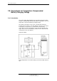

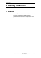


Installing I/O Modules
Installation Handbook, AutroSafe Interactive Fire Alarm System, Release 3, 116-P-ASAFE-FA/DE,
Rev. J, 2011-12-06,
Autronica Fire and Security AS
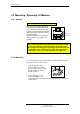
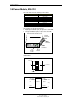
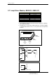
3.7 Loop Driver Module, BSD-310 / BSD-311
Screw Terminal no. Signal
1 OUT + (+24V)
2 OUT - (0V)
3 Shield
4 IN +
5 IN -
6 Shield
7 F/S +
8 F/S -
9 Chassis
10 Chassis
Green indicator, H5. Communication indicator that gives a pulsing
green light during traffic.
Red indicator, H1. Fail_Safe indicator that gives a steady red light if
a communication failure occurs, i.e. the system does not respond to
an alarm.
Schematics
24V DC Out
In
1
2
4
5
6
3
+
-
+
-
Detector
3
1
2
3
2
1
3
1
2
BSD-310
8
7
-
+
F/S Signal
From previous Loop Driver Module
To next Loop Driver Module
Loop
Driver
Module
Screw
terminal 1
Red
indicator
H1
Green
indicator
H5
Front view when mounted on rail
Screw
terminal 10