
User guide

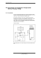


Installing I/O Modules
Installation Handbook, AutroSafe Interactive Fire Alarm System, Release 3, 116-P-ASAFE-FA/DE,
Rev. J, 2011-12-06,
Autronica Fire and Security AS
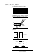
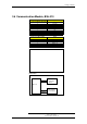
3.5 Power Module, BSS-310
The I/O module has the following connections:
Screw Terminal no. Signal
1 +24 V Input
2 +24 V Input
3 0 V Input
4 0 V Input
5 Chassis
6 Chassis
7 Not in use
8 Not in use
9 Not in use
10 Not in use
The module has two green indicators;
Right green indicator (H1) - the presence of 24V DC
Left green indicator (H2) - the presence of 5V DC
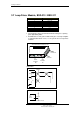
Schematics
Screw
terminal 1
Green
indicator
H1 (24V)
Green
indicator
H2 (5V)
Front view when mounted on rail
Screw
terminal 10
Plug-in
Connection
Block
4
BSS-310
Chassis
5
+
BSF-310B
-
I/O Modules
3
1
5
2
4
6
+
-
+ 24V reg
+ 5V reg
BSS-310
0V
Internal
Internal
Internal
24V DC input
Chassis
0V
1
5
3