
User guide


Internal Cable Connections
Installation Handbook, AutroSafe Interactive Fire Alarm System, Release 3, 116-P-ASAFE-FA/DE,
Rev. J, 2011-12-06,
Autronica Fire and Security AS
2.4 Shielding and Earthing
2.4.1 Introduction
Due to requirements in EN54 and generic EMC-requirements, it is
very important to keep in mind how to make earthing and shielding of
cables when installing.
2.4.2 Definitions
Protective Earth
Termination point to the external protective earth. In AutroSafe this
is the connection at the BSS-103A/02 block terminal (terminal 1).
Protective Earth to
Cabinet
Main earth connection which ensures that the cabinet always is
connected to earth.
Note: Must not be removed or unscrewed.
Chassis
Electrical connection to the steel cabinet. A screw on the rear
mounting plate (up left to the Power Supply) is provided for this.
This is in turn connected to the Protective Earth for human
protection and earthing.
Shield
Termination point for the shielding of cables, where provided.
0V_BAT
Reference point for the battery circuit (isolated from earth/chassis).
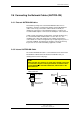
2.5 Power Supply and Battery Connections
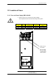
2.5.1 Connecting 230 VAC to Power Supply BSS-103A/02
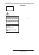
NOTE!
The illustration below shows an overview of the mains connection (230 VAC) to the Power
Supply BSS-103A/02. The connection of mains power is done during commissioning. Until then,
do not
connect the mains power .
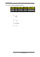
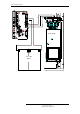
Chassis
Power
Supply
BSS-
103A/02
Protective Earth
(terminal)
Schematic outline inside cabinet - Front view
Protective
Earth to
Cabinet
Protective
Earth
230 V AC
Detail drawing of Power
Supply / upper part of Fire
Alarm Control Panel /
Controller
Live Neutral