
User guide

Verifying the System after
an Upload
Commissioning Handbook, AutroSafe Interactive Fire Detection System, Release 4, 116-P-ASAFE-COMMISS/EGB Rev.D, 2011-09-14,
Autronica Fire and Security AS
Page 36
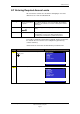
Step Description
all respective outputs are activated.
8
Test the action of any auxiliary operating functions (disabling, cancelling and resetting
buttons).
9
Check the alarm transference outputs by connecting from outgoing outputs (potential free
relay and 24V output) activated by alarm in a zone.
10
Check the fault warning function from detector zones by removing a detector in each zone.
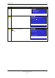
Activate a fault (remove battery fuse) and observe:
- the Fault indicator starts to blink
- a fault warning is displayed
- the internal buzzer is turned ON
- the Fault Warning Routing Equipment (FWRE) output is activated (if any)
11
Verify all conditions, i.e.:
- Fire Alarm condition
- Fire Warning condition
- Fault Warning condition
- Disablement condition
- Test condition
12
On completion of checks, ensure that only the green "Power" indicator is ON when the
panel is in its idle state (normal operation).
13
Enable alarm transference to the Fire Alarm Routing Equipment -FARE output.
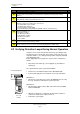
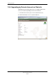
9.2 Verifying Detection Loops During Normal Operation
It may be necessary to verify the detection loops (checking the loop
topology, the types of loop units, the location of loop units, the Loop
Sequence Indexes, etc.) during normal operation using the AS-2000
Loop Diagnostic Tool.
Before applying the tool, prepare the system for the verification as
follows:
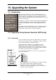
Enter the Service Menu (5), select Upgrade (5), then Reboot
System (6).
The system will now enter system fault condition.
Remove fuse A1 and A2 from the Power Board BSF-400.
Connect and apply the tool, and do the necessary verifications.
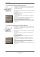
Alternative 1:
Disconnect a detection loop. Use the AS-2000 Was-box to verify
the loop. Perform a verification for each loop in turn.
Alternative 2:
Disconnect the ribbon cable to BSL-310. Connect the AS-2000.
Run an initialization.
When the verification is completed, disconnect the tool/PC, re-
connect the cables, then re-place the fuses.
Reboot the system again.
1
2
3
AFB A
AFB A"
AFB CT A
4
5
6
A
FB Earth Fault Sen
s
AFB B
AFB B"
7
8
AFB CT B
A
FB Earth Fault Sen
s
J2
J19
S
High Low
J24
J18
+
B
0V
+
A2
0V
+
A1
X11 X10
S5
AFB Earth Fault Off
AFB Earth Fault On
1
OFF
ON
2
OFF
ON
Power Board BSF-400
Fuse A1
and A2