Release 4 Commissioning Handbook AutroSafe Interactive Fire Detection System 116-P-ASAFE-COMMISS/EGB Rev.
COPYRIGHT © This publication, or parts thereof, may not be reproduced in any form, by any method, for any purpose. Autronica Fire and Security AS and its subsidaries assume no responsibility for any errors that may appear in the publication, or for damages arising from the information in it. No information in this publication should be regarded as a warranty made by Autronica Fire and Security. The information in this publication may be updated without notice.
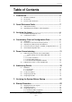
Introduction Table of Contents 1. Introduction .......................................................................5 1.1 1.2 1.3 About the Handbook.......................................................................... 5 The Reader ....................................................................................... 5 Reference Documentation................................................................. 6 2. Quick Reference Guide ....................................................7 2.1 2.
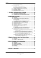
Introduction 8.4 8.5 8.6 8.7 8.3.3 Configuration Missing.............................................................. 27 Configuration File .............................................................................. 28 8.4.1 Name, Format and Extension ................................................. 28 8.4.2 Copying the Zip File to a USB Stick ........................................ 28 Uploading Configuration Files to the System .................................... 29 Configuration Mismatch........
Introduction E-1676 1. Introduction This product contains static-sensitive devices. Always use an antistatic wrist strap / ground bracelet to avoid any electrostatic discharge. 1.1 About the Handbook This handbook is intended to provide all necessary information for the commissioning of the AutroSafe Interactive Fire Detection System, Release 4.
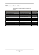
Introduction 1.3 Reference Documentation The table below shows an overview of the technical marketing documentation for AutroSafe Interactive Fire Detection System, Release 4.
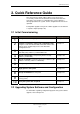
Quick Reference Guide 2. Quick Reference Guide This quick reference guide outlines all the necessary steps to successfully commission the AutroSafe Interactive Fire Detection System the very first time, assuming that the system software is already uploaded to the system, and no configuration files have been uploaded. Configuration upgrade and system software upgrade are described in a separate chapter (Chapter 10). 2.
Verifying the Loops 3. Verifying the Loops 3.1 AS-2000 Loop Diagnostic Tool All loops should be verified with the AS-2000 Loop Diagnostic Tool before startup. Although this is presumably already done at an earlier stage (shortly after the installation), it is recommended that all loops are verified once again in case minor changes have been done. By doing this, you will eliminate possible problems which could occur during the startup procedure and upgrading of configuration data.
Consistency Check of Configuration Data 4. Consistency Check of Configuration Data 4.1 Introduction NOTE: To ensure a problem-free upload of configuration data, always perform a consistency check, using the results from the AS-2000 verification and the data that has been configured by means of the AutroSafe Configuration Tool. 4.2 Parameters Used for the Consistency Check The table below provides a description of two of the parameters that are used for the consistency check.
Consistency Check of Configuration Data 4.3 Importing Loop Data from the AS-2000 Tool The AutroSafe Configuration Tool features an Import command allowing you to import loop data directly from the AS-2000 Loop Diagnostic tool. In this way, it is possible to ensure that the point types and sequence indexes in the configuration will be identical to the real loop. Tag Names and optional Detection Zones (DZs) will be assigned to the points during import.
Power Commissioning 5. Power Commissioning 5.1 Addressing Power Boards on the AutroFieldBus 5.1.1 Switch Settings on Power Board BSF-400 The board is configured by means of two switches: Rotary switches X10 and X11 - AutroFieldBus address switch. Each Power Board is given a unique address. Dipswitch S5/S6 – configuration (refer to dipswitch table, chapter 5.1.4) 5.1.2 Location of Switches The location of the dipswitch S5 and S6, plus the rotary switches X10 and X11 are shown on the drawing.
Power Commissioning S5 1 2 AFB Earth Fault Off OFF OFF AFB Earth Fault On ON ON Dipswitch S5 J2 1 2 3 4 5 6 7 8 AFB A AFB A" AFB CT A AFB Earth Fault Sense AFB B AFB B" AFB CT B AFB Earth Fault Sense 1 1 2 3 4 5 6 6 A A R F F F F1 A1 + 0V J19 S1 Reset X10 Low B1 + 0V 8 7 6 5 4 3 2 1 X11 High A2 + 0V J18 J24 F2 S1 Reset button AutroFieldBus Address Switch X10, X11 A F3 B1 F2AL F4 B2 F2AL J23 B2 + 0V F5 C1 F2AL J22 C1 + 0V F6 C2 F2AL 1 1 2 3 4 5 6 Earth Fa Battery AFB pre Battery 6
Power Commissioning 5.1.3 AutroFieldBus Addresses Each AutroFieldBus unit/Power Board BSF-400 on an AutroFieldBus must be assigned a unique address by means of an rotary switch (see previous page). The drawing below shows the AutroFieldBus connections on the main terminal block, list L1 mounted on a DIN rail inside the cabinet (BS-420/BC-420). The first AutroFieldBus unit is connected to the terminals L1.9 / L1.11 (AFB A). The last unit is connected to L1.3 / L1.5 (AFB B).
Power Commissioning 5.1.4 Power Board Configuration Switches The settings of the dipswitches are read during startup. If the switches are changed for any reason, the changes will not take affect until the Power Board is restarted (pressing the reset button S1 on the Power Board). Dipswitch table – S5 S5.1 OFF ON S5.
Power Commissioning 5.2 Calibration Procedure - Power Unit BPS-410 When using Power Unit BPS-410 (including a 24V/10A power supply), a calibration procedure must be performed. This is necessary in order to obtain a correct temperature compensated charging voltage to the batteries.
Addressing Panels 6. Addressing Panels 6.1 Definitions 6.1.1 System ID A panel’s System ID indicates which system and unique configuration a panel belongs to. All panels communicating on the same AutroNet network must have the same System ID, usually set to 01 (switch setting; rotary switches X5 and X3). The System ID also determines the specific number series of the IP Addresses (which are set during commissioning by operating the AutroSafe menu).
Addressing Panels 6.2 Location of Switches The switches are located on the lower left hand side of the BSA-400 circuit board, easily accessible through the hole in the metal cover. The BSA-400 circuit board X6 X4 X5 X3 S2 Commissioning Handbook, AutroSafe Interactive Fire Detection System, Release 4, 116-P-ASAFE-COMMISS/EGB Rev.
Addressing Panels 6.3 Assigning System IDs The settings of the rotary switches X5 and X3 determine the panel’s System ID, i.e. which system and unique configuration the panel belongs to. All panels communicating on the same AutroNet network must have the same System ID, usually set to 01. X5 is set to 0 X3 is set to 1 If there is a second network, this network can be set to 02, a third can be set to 03, etc. Switch X5 corresponds to the most significant digit in the address.
Addressing Panels 6.4 Assigning Panel IDs The settings of the rotary switches X6 and X4, plus the settings of dipswitch S2 (type of panel) determine the Panel ID. Each panel in the system must be assigned a unique Panel ID (switch settings) which must correspond to the Panel ID given in the specific configuration in the Configuration Tool. Note that a standalone Fire Alarm Control Panel BS-420 always has Panel ID=00. Switch X6 corresponds to the most significant digit in the address.
Addressing Panels Example: A network configuration consists of two BS-420 panels, one BS-430 panel and one BU-BV-420 panel (a BU-BV-420 panel defined as a Fire Brigade Panel).
Verifying the System Before Startup 7. Verifying the System Before Startup Before verifying the system, all parts in all system units must be installed and properly connected, and all panels and AutroFieldBus units must be addressed correctly.
Startup Procedure 8. Startup Procedure When the AutroFieldBus units (Power Boards BSF-400 and all panels) have been addressed, and the configuration files have been generated by means of the AutroSafe Configuration Tool, power is to be applied to the system. The commissioning can take place from any Fire Alarm Control Panel BS-420 or Operator Panel BS-430 in the system (freely selected panel). During uploading of configuration files (or system software), the system may report possible faults.
Startup Procedure 8.2 IP Number Structure Example: 172.16.101.21 172.17.101.117 172.16.101.21 Panel ID (+20), unique ID assigned to each panel System ID (+100), identifies which system and unique configuration the panel belongs to. Ethernet Port ID, referring to one of the two redundant network ports (each panel assigned to two consecutive numbers) Network Number, common number for all panels belonging to the same network 8.
Startup Procedure 8.3.1 Automatic Addressing Mode Selecting Automatic Addressing Mode will assign default IP Addresses to all panels. Autrosafe software version 4.3.1 Config model 4.4 Market version: Land Switch address 01-001 Searching for panels, found 2 BS-420 01.01: 4.3.1 BU-420 01.01: 4.3.1 IP not set, select addressing mode: 1. Automatic 2. Manual Press 1 to select Automatic Addressing. Autrosafe software version 4.3.1 Config model 4.
Startup Procedure To save the addressing, press 1. Autrosafe software version 4.3.1 Config model 4.4 Market version: Land Switch address 01-001 Searching for panels, found 2 BS-420 01.01: 4.3.1 BU-420 01.01: 4.3.1 Config missing Verify config on switch settings 3. Upgrade software 4. Upgrade config 6. Reboot panels When the IP addressing is completed, proceed to chapter 8.5, Uploading Configuration Files.
Startup Procedure 8.3.2 Manual Addressing Mode If you have to take into consideration IP Addresses that are already assigned to other existing components on the network, IP Addresses can be set manually. In this way, you can freely select IP Addresses within the given ranges of 3 different number series, each representing a specific class (Class A, B or C). Note that the standard IP version 4 addressing is applied.
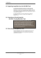
Startup Procedure 8.3.3 Configuration Missing If no configuration has been uploaded to the system previously, the message “Config Missing” will be shown. Autrosafe software version 4.3.1 Config model 4.4 Market version: Land Switch address 01-001 Searching for panels, found 2 BS-420 01.01: 4.3.1 BU-420 01.01: 4.3.1 Config missing 1. Import config from USB stick 2. Reboot all panels Commissioning Handbook, AutroSafe Interactive Fire Detection System, Release 4, 116-P-ASAFE-COMMISS/EGB Rev.
Startup Procedure 8.4 Configuration File 8.4.1 Name, Format and Extension The AutroSafe Configuration Tool generates the following compressed file: AC_Vnn_mm_filename.tar.bz2 AC AutroSafeConfiguration Vnn Main interface model number mm Sub interface model number filename The AutroSafe configuration file name, valid characters are [0-9a-zA-Z] and underscore '_'. If the filename contains non-valid characters the file name will be replaced with the name "Configuration".
Startup Procedure 8.5 Uploading Configuration Files to the System When the IP addressing is completed, configuration files can be uploaded to the system from one central point (any panel in the system). Autrosafe software version 4.3.1 Config model 4.4 Market version: Land Switch address 01-001 Searching for panels, found 2 BS-420 01.01: 4.3.1 BU-420 01.01: 4.3.1 Config missing Verify config on switch settings 3. Upgrade software 4. Upgrade config 6. Reboot panels Press 4 (Upgrade config).
Startup Procedure The following will appear on the display: Autrosafe software version 4.3.1 Config model 4.4 Market version: Land Switch address 01-001 Searching for panels, found 2 Transfering to panels (1 of 2) Autrosafe software version 4.3.1 Config model 4.4 Market version: Land Switch address 01-001 Searching for panels, found 2 Unpacking to panel (1 of 2) Please wait, upgrade in progress Autrosafe software version 4.3.1 Config model 4.
Startup Procedure Selection 3. “Upgrade Software” is shown only if the software is not already upgraded. Autrosafe software version 4.3.1 Config model 4.4 Market version: Land Switch address 01-001 Searching for panels, found 2 Rebooting the system Please wait, upgrade in progress When the system is rebooted, the system will enter normal operation mode. To run initialization, press 1 or wait (countdown).
Startup Procedure 8.6 Configuration Mismatch If the system has an existing configuration, and the new configuration you have uploaded does not match the installation in question, the message “Config Mismatch” will appear. If the software to be used is not supported by the config model, the message “Config Model Mismatch” will appear (see screenshot below). The “Config Faulty” message will appear if the configuration files for some reason are corrupt.
Startup Procedure 8.7 Entering Required Access Levels All user interface controls are classified as belonging to one of the different access levels described below: Access Level Access Remedy 1 No key or password required. Accessible by members of the general public. All mandatory indications are visible at access level 1 without prior manual intervention. Description 2 Access by key. Accessible by persons having a specified responsibility for safety. 3 Password restricted.
Startup Procedure Step 3 Actions to be taken Display Indication To select ACCESS LEVEL 3, press 3. SYSTEM 19:23 ACCESS LEVEL 3 1 ENTER ACCESS LEVEL 3 2 LEAVE ACCESS LEVEL 3 3 SET PASSWORD 4 To enter ACCESS LEVEL 3, press 1. SYSTEM 19:23 ACCESS LEVEL 3/ENTER ACCESS LEVEL 3 Enter password: 5 Enter the password, then press SYSTEM 19:23 ACCESS LEVEL 3/ENTER ACCESS LEVEL 3 twice.
Verifying the System after an Upload 9. Verifying the System after an Upload 9.1 General System Verification Procedure To ensure that the system works properly during normal operation after an upload, the whole system (control panel, detectors, control functions) should be verified after an upload. Step Description 1 To test the panel indicator lights and internal buzzer, press and hold the Reset button for at least 5 seconds. All indicators are lit and the buzzer is turned on.
Verifying the System after an Upload Step Description all respective outputs are activated. 8 Test the action of any auxiliary operating functions (disabling, cancelling and resetting buttons). 9 Check the alarm transference outputs by connecting from outgoing outputs (potential free relay and 24V output) activated by alarm in a zone. 10 Check the fault warning function from detector zones by removing a detector in each zone.
10. Upgrading the System 10.1 Introduction NOTE: When upgrading the system by means of a USB memory stick, do not remove the USB stick from the USB port until you are sure that the upgrade procedure is completed. Enter the menu “View Upgrade Status” to follow the progress and verify that the procedure is completed. After the very first startup of a system, a running system can be upgraded at any time using the service menu commands (shown in the next chapter).
Upgrading the System 10.2.2 Upgrading Software During Normal Operation Note that before executing this command, insert the USB memory stick with the correct and valid file into one of the USB ports on the BSA-400 Controller Board. After the stick is inserted, wait at least 5 seconds before executing the command. From the panel front, press 5 to enter the Service Menu (Access Level 3). To select Upgrade, press 5. To Upgrade SW press 1.
Upgrading the System 10.3 Upgrading when Panels are Added/Removed If panels are added or removed, or it is necessary to change IP addresses, a reboot must be executed. The continuing procedure is similar to the startup procedure, chapter 8. Go to chapter 8 and follow the procedure. 10.4 Upgrading if IP Addresses are to be Changed If it is necessary to change IP addresses, a reboot must be executed. The continuing procedure is described in the startup procedure, chapter 8.
Upgrading the System 10.6 Upgrading by Remote Access to a Web site Upgrading can be performed by means of a computer with remote access to a web site providing several service functions. From the Service menu, press 6 to select Remote Access. For further information, refer to separate handbook. Commissioning Handbook, AutroSafe Interactive Fire Detection System, Release 4, 116-P-ASAFE-COMMISS/EGB Rev.
Upgrading the System 10.7 Upgrading Software Version 4.0.1 to 4.1.1 10.7.1 General This chapter deals with the upgrade from software version 4.0.1 to 4.1.1. IMPORTANT: Follow the upgrade procedure as described in detail below. During the upgrade to software version 4.1.1, the system will enter system fault condition. Do NOT disconnect the mains power or press the front panel’s Reset System button. Press the front panel’s Mute button to silence the buzzer.
Upgrading the System 10.7.3 Preparing a System in System Fault Condition To perform a hard reset, push and hold down the reset button S5 until the red LED indicator D20 and D21 are lit for a short moment and you hear a click from the relay. Reset button S5 Controller Board BSA-400 LEDs D20 D21 D13 D17 D3 D23 D2 D18 D15 D22 D1 D19 D16 LEDs The system will now detect all running panels, and prompt you to reboot the entire system (all running panels).
Upgrading the System 10.8 Upgrading Software Version 4.0.1 or 4.1.1 to 4.3.1 This chapter shows examples of how to upgrade from software version 4.0.1 or 4.1.1 to 4.3.1. 10.8.1 Example 1: Upgrading all Panels from SW Version 4.0.1 or 4.1.1 to 4.3.1 All panels have software version 4.0.1 or 4.1.1 installed. Upgrade all panels simultaneously by using a USB stick including program version 4.3.1 (or later when available). 10.8.2 Example 2: Adding a BS-420/BS-430 panel with SW Version 4.1.
10.8.4 Example 4: Adding a Panel with SW Version 4.3.1 to a System Running on SW Version 4.1.1 A system is running on software version 4.1.1. A new panel with software version 4.3.1 installed is going to be added. Start the system without connecting the new panel to the AutroNet. Upgrade the system to run version 4.3.1 by using a USB stick. Connect the new panel to the system AutroNet. Restart the system and upgrade the new system configuration data by using an USB stick.
Startup Procedure for a Dual Safety System 11. Startup Procedure for a Dual Safety System 11.1 Introduction This chapter describes the initial startup procedure of a system consisting of a Primary System and a Secondary System (AutroSafe Dual Safety concept). In principle, the startup procedure is identical to the startup procedure of a normal system, however, the startup procedure must be carried out for each system in turn (both the Primary System and the Secondary System).
Startup Procedure for a Dual Safety System 11.2 Guidelines – Startup Procedure The following guidelines apply: Step Action Chapter 1 Perform the following actions for both the Primary and the Secondary System: Verify the detection loops by means of the AS-2000 tool. Perform a consistency check of the configuration data using the results from the AS-2000 verification and the data that has been configured by means of the AutroSafe Configuration Tool.
Startup Procedure for a Dual Safety System Step Action Chapter 4 Apply power to the panel belonging to the Secondary System, then: Select Automatic addressing mode to assign an IP Address to each panel. Upload configuration data to all panels from the panel in question. Start system, perform an initialization. 8.1, 8.3, 8.5 5 Apply power to the panel belonging to the Primary System, then: Select Automatic addressing mode to assign an IP Address to each panel.
Fault Messages during Uploading 12. Fault Messages during Uploading 12.1 Introduction During uploading, the system may report possible faults. If such fault messages occur, the panel in question should be rebooted by means of the reset button S5 on the Controller Board BSA-400 inside the panel. To perform a hard reset, push and hold down the reset button S5 (approximately 6 to10 seconds) until the red LED indicators D20 and D21 are lit for a short moment and you hear a click from the relay. 12.
Fault Messages during Uploading 12.5 Fail to Unpack Files If the unpacking of files on a panel is not successful, one of the following error messages may occur: "Failed to unpack, file system error on panel " "Failed to unpack, panel error on panel " Commissioning Handbook, AutroSafe Interactive Fire Detection System, Release 4, 116-P-ASAFE-COMMISS/EGB Rev.
Reader’s Comments . Reader’s Comments Please help us to improve the quality of our documentation by returning your comments on this manual: Title: Commissioning Handbook, AutroSafe Interactive Fire Detection System, Release 4, Ref. No.: 116-P-ASAFE-COMMISS/EGB Rev.D, 2011-09-14 Your information on any inaccuracies or omissions (with page reference): Please turn the page Commissioning Handbook, AutroSafe Interactive Fire Detection System, Release 4, 116-P-ASAFE-COMMISS/EGB Rev.
Reader’s Comments Suggestions for improvements Thank you! We will investigate your comments promptly.
Autronica Fire and Security is an international company, headquartered in Trondheim, one of the largest cities in Norway. The company is owned by United Technologies Corporation and employs more than 319 persons with experience in developing, manufacturing and marketing of fire safety equipment.