Operator's Handbook Autroprime Interactive Fire Detection System 116-P-APRIME-OPERATE/FGB Rev.
COPYRIGHT © This publication, or parts thereof, may not be reproduced in any form, by any method, for any purpose. Autronica Fire and Security AS and its subsidaries assume no responsibility for any errors that may appear in the publication, or for damages arising from the information in it. No information in this publication should be regarded as a warranty made by Autronica Fire and Security AS. The information in this publication may be updated without notice.
Table of Contents Table of Contents 1. Introduction.......................................................................5 1.1 1.2 1.3 1.4 About the Handbook ......................................................................... 5 The Reader ....................................................................................... 5 Reference Documentation ................................................................ 5 Components ........................................................................
Table of Contents 5. In the Event of a Fire Alarm .............................................27 5.1 5.2 Indications in the Event of a Fire Alarm ............................................ 27 Actions to be Taken in the Event of a Fire Alarm.............................. 27 6. In the Event of a Pre Alarm ..............................................32 6.1 6.2 Indications in the Event of a Pre Alarm ............................................. 32 Actions to be Taken in the Event of a Pre Alarm ......
Table of Contents 13.4 13.5 13.6 13.7 13.8 13.9 13.10 13.11 13.12 Enabling Detection Zones ................................................................. 52 Enabling Alarm Zones ....................................................................... 52 Enabling Points ................................................................................. 52 Enabling Fire Alarm Devices............................................................. 52 Enabling Outputs (Loop Outputs/Local Outputs) ...............
Table of Contents 17. Appendix ...........................................................................73 17.1 Menu Structure.................................................................................. 73 18. Reader’s Comments .........................................................77 Operator's Handbook, Autroprime Interactive Fire Detection System, 116-P-APRIME-OPERATE/FGB Rev.
Introduction 1. Introduction 1.1 About the Handbook This handbook provides the information necessary to operate the Autroprime Interactive Fire Detection System (hereby called Autroprime) from the Fire Alarm Control Panel, including; Fire Alarm Control Panel BS-200, BS-200L and BS-200M Operating Panel BS-210 (an integrated part of the Fire Alarm Control Panel) Repeater Panel BS-211 Information Panel BV-210 Fire Brigade Panel BU-210 1.
Introduction 1.4 Components The Autroprime Interactive Fire Alarm System comprises the following components (EN-54) : Component Abbreviation Point Control and indicating equipment c.i.e. Power Supply - Fire Alarm Devices FAD Fire Alarm Routing Equipment FARE Control for Fire Protection Equipment FPE Fault Warning Routing Equipment FWRE Fire Alarm Receiving Station Fault Warning Receiving Station Automatic Fire Protection Equipment - Description Ref. Detector or manual call point.
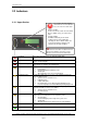
The Operator Panel 2. The Operator Panel 2.1 Introduction The Operator Panel BS-210, including an upper and a lower section, is an integrated part of the Fire Alarm Control Panel BS-200, BS-200L and BS-200M. The Repeater Panel BS-211 is identical with the Operator Panel, with the exception of the alphanumeric keypad at the lower section.
The Operator Panel 2.2 Indicators 2.2.1 Upper Section The circular red alarm indicator shows that one or more detection zones are in the fire alarm state. Pulsing red light: In the event of a fire alarm. The Fire Alarm Devices (FAD), (if any), are still in active state. Steady red light: All FADs activated by the fire alarm condition have been deactivated by operating the Silence Alarms button. The control and indicating equipment still remain in the fire alarm condition.
The Operator Panel 2.2.2 Lower Section Delayed Activation Annunciator Fault Remote Call Fault Annunciator Disabled Remote Call Disabled Steady yellow light indicates that Immediate Output Actioning has been changed to delayed output actioning (manually or automatically by using the Day/Night function), meaning that a delay period is active for Fire Alarm Devices (FAD), Fire Alarm Routing Equipment (FARE) and all other outputs that are connected to the detection zone of this type.
The Operator Panel 2.3 The Panel Display During normal operation, the panel display is always backlit. The panel display has 8 lines of 40 characters. Autroprime features a scrollbar functionality. A mark in a vertical scrollbar on the right hand side of the display gives an approximate indication of how many lines there are above and below the line which is currently highlighted. For example, if there are a total of 6 alarms (6 lines), the mark will be positioned in the middle of the scrollbar. 2.
The Operator Panel Function Buttons (lower section) Button Prolong Delay (black) Description Access Level Applies to detection zones that are defined as Delayed Action Detection Zones. 1 Used to prolong the delay period. A global functionality. The delay is divided into two delay periods, Initial Delay, T1 (configurable) and Prolonged Delay, T2 (configurable). The (T1) delay period starts when a Fire Alarm signal from a point is received.
The Operator Panel 2.4.2 More Events button More Events button (upper section) Button More Events (black) Description Access Level Used to scroll downwards among events in the currently active window. Available only if there are more events to be displayed in the window than what is currently displayed (i.e. the number of lines exceeds 6). 2 In addition, a lamp test can be performed by pressing and holding the button for at least 10 seconds.
The Operator Panel 2.4.4 Manoeuvre and Utility Buttons Manoeuvre and Utility Buttons (lower section) Button When accessible (mode) Select Enter Description Used to select one of several lines (items). Multiselect is possible by holding down the Select button and at the same time selecting all lines by scrolling with the up or down arrow buttons. It is also possible to scroll among several lines and select one-by-one by using the Select button. When the cursor is on a list item.
The Operator Panel 2.5 Internal Buzzer Each panel provides an internal buzzer which is activated as described below. If more than one condition is present simultaneously, the buzzer will reflect the condition which has the highest priority. The internal buzzer is activated in the cases of: System Fault Alarm Pre Alarm Fault Supervisory The internal buzzer can be silenced by pressing the Mute Panel button.
Operation Mode 3. Operation Mode 3.1 Loop Topology Presentation When the panel is turned on and the initialization procedure is completed, the panel will recognize detectors and other loop units and the system topology is shown in the display. 3.2 The Panel’s Idle State The panel can be in either Operation Mode or Menu Mode. When no one is operating the panel and no button has been pressed, the panel will always be in Operation Mode, provided that the system is in quiescent condition (see below).
Operation Mode 3.4 Alarm Levels A detector may signal different levels of alarm, indicating the amount of smoke or gas currently present. These are; Fire Alarm Level (the highest level) Pre Alarm Level Whenever a detector detects a transition from one alarm level to another (from lower level to the highest level), this event is reported to the system as a Pre Alarm or Fire Alarm signal, which in turn will initiate the appropriate actions. 3.
Operation Mode 3.6 How Events are Presented in the Display The different events, for example, «In the Event of a Fire Alarm», are presented in Operation Mode. The example below shows a situation where 2 detection zones are in alarm state. The first and the last detection zone are shown in the display, including information on the name of detectors and locations. The total number of zones is shown in the upper right corner of the display. Total number of detection zones in alarm state 3.
Operation Mode 3.8 Resounding the Internal Buzzer When pressing the Mute Panel button in an alarm condition, the internal buzzer will automatically be resounded in the following cases: if any new event occurs (for example, a detection zone enters the Fire Alarm state) after a timeout period, if the cause for making it sound is still present 3.9 Resounding Fire Alarm Devices When pressing the Silence button in the event of an alarm, all Fire Alarm Devices (FADs) will be deactivated.
Operation Mode 3.10.2 Point Disablements A general rule is that a Point may be disabled by one or more disablement sources simultaneously. In order to be enabled, the Point must be enabled from all these disablement sources. Example: A Point is disabled from a Zone (Detection Zone disable command issued from the Fire Alarm Control Panel) and from a Disable Input Unit.
Operation Mode 3.11 Alarm Organization 3.11.1 Detection Zones with Different Properties When handling events in Operation Mode, it is important to be aware of how the alarm organization is configured, that is, the system’s detection zone configuration.
Operation Mode 3.11.4 Dependency Action Detection Zones In areas where points may be exposed to a high level of pollution, for example, unwanted alarms may occur. In order to avoid this problem, the Dependency Action alarm organization is used. A fire alarm signal from a single detector in a system defined as Dependency Action will initiate no actions, i.e.
Operation Mode 3.11.5 Delayed Action Detection Zones Delays to any output depends on the Day Mode operation of the system (i.e. the LED for Delayed Action is ON). In Night Mode (i.e. the LED for Delayed Action is OFF) all outputs will be activated at first point in alarm. When the operator panel receives a fire alarm signal from a point in a Delayed Action detection zone (configurable), the actioning of outputs to Fire Alarm Devices (FAD) and/or Fire Alarm Routing Equipment (FARE) can be delayed.
Operation Mode T1 for different detection zones may start at different times, however, when Prolong Delay has been pressed, T2 for all detection zones will start at the same time. If one or more Delayed Action detection zones have entered the Fire Alarm state and are in their T1 or T2 periods, the delayed actions can be immediately initiated by pressing the Activate Outputs button.
Operation Mode 3.11.7 SOLAS Detection Zones Note: Applies to Fire Alarm Control Panel BS-200M only. A detection zone configured as SOLAS Detection Zone (Safety of Life at Sea), has a two-minute delay from when a Point enters an alarm condition until the associated Detection Zone initiates the activation of the configured Fire Alarm Devices (FADs) and outputs.
Operation Mode Silent Alarm Any fire alarm signal will be indicated at the panel without any delay, and this is the Silent Alarm level. An output may be configured to be activated at this level, as an example to trigger a coded message through a voice alarm system or an output to make on site technical personnel aware of the situation. The delay timer T1 will be started and a countdown timer will be shown in the display. For a Delayed detection zone the operator may now initiate a prolonged T2 period.
About «In the Event of….» 4. About «In the Event of….» The subsequent chapters - In the event of…..- deal with different events that may occur; Chapter In the event of….. Chapter 5 a fire alarm Chapter 6 a fire alarm with alarm delay (in a Delayed Action detection zone - immediate output actioning disabled) Chapter 7 a pre-alarm Chapter 8 faults Chapter 9 supervisory condition The list above covers the most common events.
In the Event of a Fire Alarm 5. In the Event of a Fire Alarm 5.1 Indications in the Event of a Fire Alarm One or several fire detectors or manual call-points in one or several detection zones are signalling a Fire Alarm. The red Alarm indicator is pulsing. The total number of Detection Zones. The text display presents the first and last (if several) detection zones in alarm state and their location. By operating the menu, detailed information is available.
In the Event of a Fire Alarm Step Actions to be taken 3 Use the arrow down (/arrow up) button and scroll to observe the detection zones and point(s) in alarm state. Comments: 4 Investigate the scene(s) and carry out the necessary actions. 5 To select a point, scroll with the arrow up/down buttons. 6 To view detailed point information, press Display Indication Audible Indication In this example, a total of 2 detection zones are in alarm state.
In the Event of a Fire Alarm Step Actions to be taken Display Indication Audible Indication If no points are signalling an alarm, the system is reset and the display will return to its idle state. Comments: The red Alarm indicator goes off. The red Remote Call indicator goes off (if a FARE output is configured and applied). If there are points still signalling an alarm when the system has been reset, go to step 9. The point(s) still in alarm are shown on the display.
In the Event of a Fire Alarm Step Actions to be taken Display Indication Audible Indication will appear to the left of each the selected points). To multiselect points one-by-one, press the Select button to mark a point, then scroll to another point in the list and press the Select button once more to mark the next one. 13 Press the Function button , then press twice.
In the Event of a Fire Alarm Step Actions to be taken Comments: Display Indication Audible Indication If there are no points signalling a fire alarm, the system is reset. The panel enters its idle state. The red Alarm indicator goes off. The red Remote Call indicator goes off (if a FARE output is configured and applied). Operator's Handbook, Autroprime Interactive Fire Detection System, 116-P-APRIME-OPERATE/FGB Rev.
In the Event of a Pre Alarm 6. In the Event of a Pre Alarm 6.1 Indications in the Event of a Pre Alarm A detector in one of the detection zones has entered Pre Alarm state. The red Pre Alarm indicator is pulsing. The text display presents the detection zone(s) in Pre Alarm state and their location. By operating the menu, detailed point information is available. The red More Events indicator is pulsing if several detection zones are signaling a Pre Alarm. The internal buzzer is activated.
In the Event of a Pre Alarm Step Actions to be taken Comments: 4 Investigate the scene(s) and carry out the necessary actions. 5 To select a point, scroll with the arrow up/down buttons. 6 To view detailed point information, press Display Indication Audible Indication In this example, a total of 3 points are in Pre Alarm state. If you want to view detailed point information before investigating the scene(s), go to step 5. If not, investigate the scene(s), then go directly to step 7.
In the Event of a Fire Alarm with Alarm Delay 7. In the Event of a Fire Alarm with Alarm Delay 7.1 Indications - Fire Alarm with Alarm Delay A point is sending an alarm signal from a Delayed Action detection zone and the system is set to Day Mode (alarm delay is active). NOTE: An alarm from a manual call point is normally configured to give immediate actioning on the alarm outputs even though the system is set to Day Mode provided that the point has been set to Override Delay and Dependency (YES).
In the Event of a Fire Alarm with Alarm Delay Step Actions to be taken 2 To silence the internal buzzer, press the black Mute Panel button. 3 Use the arrow down (/arrow up) button and scroll to observe the point(s) in alarm state. Comments: 4 Display Indication Audible Indication The internal buzzer on the operator panel is turned off. In this example, 1 point is in alarm state. If you want to view detailed point information before investigating the scene, continue with the next step.
In the Event of a Fire Alarm with Alarm Delay Step Actions to be taken Display Indication Audible Indication point has been set to Override Delay and Dependency YES). 8 Carry out the necessary actions. 9 To silence all alarms, press the red Silence button. Comments: All Fire Alarm Devices (FAD) are deactivated. The red Alarm indicator goes steady. To manually resound the alarm zones at this stage, press and hold down the Silence button at least 5 seconds.
In the Event of Faults 8. In the Event of Faults 8.1 Indications in the Event of Faults A fault is indicated by one of the components (fire detectors, external equipment or other faults). The yellow Fault indicator is pulsing. The text display indicates the nature of the fault. By operating the menu, detailed information is available.
In the Event of Faults Step Actions to be taken Comments: 4 To select a point, scroll with the arrow up/down buttons. 5 To view detailed information for a selected point, press Display Indication Audible Indication In this example, a total of 2 points are in Fault state. If you want to view detailed information for each point in Fault state before investigating the scene(s), continue with the next step. If not, go directly to step 6. then scroll downwards to see all information.
In the Event of Faults Step Actions to be taken Display Indication Audible Indication faults. Press Comments: When a fault is acknowledged, an asterisk (*) appears to the left of the acknowledged point. When all faults have been acknowledged, the yellow Fault indicator and all other fault indicators will go steady. When all faults have been repaired, the system can be reset. 9 Press the green Reset button.
Supervisory 9. Supervisory 9.1 Indications during Supervisory The system indicates the activation of an input device, for example, a door control unit. The Supervisory indicator has a steady yellow light. The text display indicates the activation of an input device. By operating the menu, detailed information is available. The internal buzzer is activated. Only the operating buttons that are available and relevant to the current state are backlit. 9.
Supervisory Step Actions to be taken 4 To view detailed information for the selected point, press Display Indication Audible Indication then scroll downwards to see all information. 5 Investigate the scene(s) and carry out the necessary actions. Comments: 6 Now you may acknowledge the point in Supervisory state (Acknowledge).
Menu Mode 10. Menu Mode 10.1 Menu Structure The Menu Stucture is accessed when entering Menu Mode. The Menu Structure for Autroprime Interactive Fire Detection System (including all access levels) is found in Appendix. 10.2 How to Enter Menu Mode NOTE: The Silence button and the Reset button can be operated both in Menu Mode and in Operation Mode. To enter the Menu Mode from operation mode or the panel’s idle state, press and hold down the Enter button for a few seconds.
Menu Mode 10.3 How to Enter Service Mode Service Mode is entered from the main menu. Use the arrow down button to scroll down and select Enter Service Mode. Press Enter twice, then use the alphanumeric keypad and type the password that has been selected during commissioning (4 characters). To accept the password, press Enter once more. The menu selections Service and Exit Service Mode now appear in the display.
System Status 11. System Status 11.1 Introduction NOTE: Access Level 1 (no key or password required). The System Status menu is accessed from the main menu in Menu Mode. The System Status Menu is accessed with access level 1 (no key or password required). The menu gives the current status of the following conditions: Alarms Pre Alarms Faults Disablements Tests Supervisory Activated Outputs/Inputs 11.
System Status To enter the System Status menu, press the Enter button To select Alarms, press the Enter button The total number of detection zones (in this example, 2) in alarm state is shown in the upper right corner of the display. Use the arrow down button to scroll down and select a detection zone. To view detailed information for a point, press Use the arrow down button to scroll down and view all information.
Disabling 12. Disabling 12.1 Introduction NOTE: Access Level 2 (access by key). From the Disable menu you can disable the following: Detection Zone Alarm Zone Point (detectors, manual call points) Fire Alarm Device (FAD) Loop Outputs Local Outputs Loop Inputs Local Inputs Routing Equipment (FARE/FWRE) Loop IO Carriers When disabling components, a disable time span is given. The disable time span can be changed for already disabled components by entering the disable menu.
Disabling 12.3 Disabling Activated / Deactivated Components When you disable an active component, for example, a sounder issuing an alarm signal, the component will immediately switch to the OFF state without any user notification and/or confirmation cause. A disablement of a deactivated component, for example, a sounder not issuing an alarm signal, will have no immediate effect on system operation. Both activated and deactivated disabled components will remain switched off until enabled. 12.
Disabling 12.7 Disabling Fire Alarm Devices When you disable a Fire Alarm Device (FAD), the output which controls the FAD will be disabled. The FAD will thus give no audible indication. You can disable a single unit (FAD)/alarm circuit, or all units (FADs) in a selected Alarm Zone. A disable time span can be set. When the disable time span expires, the FAD(s) will automatically be enabled. The single FAD or all FADs in a selected Alarm Zone can also be enabled manually from the Enable Menu. 12.
Disabling 12.11 Disabling Loop IO Carriers You can disable a single Loop IO Carrier, or all Loop IO Carriers. A disable time span can be set. When the disable time span expires, the Loop IO Carriers will automatically be enabled. The single Loop IO Carrier or all Loop IO Carriers can also be enabled manually from the Enable Menu. 12.12 Example – How to Disable a Detection Zone The example below shows how to disable a Detection Zone. The similar procedure applies to all other selections.
Disabling Use the arrow button to scroll down and select, for example, “Detection Zone1”. Press the Function button Press the Enter button Use the alphanumeric display to enter the disable time span (hours:minutes). To accept the disablement, press the Enter button twice. Note that the yellow Disabled Function indicator is lit (steady yellow light). The detection zone and all points within this detection zone are disabled. After a period of time, the display will enter operation mode.
Enabling 13. Enabling 13.1 Introducion From the Enable menu you can enable the following components: Detection Zone Alarm Zone Point (detectors, manual call points) Fire Alarm Device (FAD) Loop Outputs Local Outputs Loop Inputs Local Inputs Routing Equipment (FARE/FWRE) Loop IO Carriers It is also possible to change the time span for the component.
Enabling 13.3 Enabling Deactivated Components Setting the arm state of a disabled deactivated component to enabled will have no immediate effect on system operation. The component will remain deactivated until its activation state is set to an active state (on alarm or on command). 13.4 Enabling Detection Zones When you enable a Detection Zone, all points within the specified detection zone will be enabled. 13.
Enabling 13.8 Enabling Outputs (Loop Outputs/Local Outputs) When you enable outputs which control Fire Protection Equipment (FPE), signals will be sent to trigger the equipment upon the activation of an output (caused by an alarm signal, input signal or output signal). You can enable a single output. 13.
Enabling 13.12 How to Execute Commands from the Enable Menu The example below shows how to enable a Detection Zone. The similar procedure applies to all other selections (except Enable Day Night Mode, see next chapter). Note that points can also be enabled from the Disablement window. To enter the Menu Mode from operation mode or the panel’s idle state, press and hold down the Enter button for a few seconds. Use the arrow down button to scroll down and select Enable. Press the Enter button .
Enabling 13.13 Enabling Delayed Activation The command Enable Delayed Activation (YES/NO) allows you to enable or disable all delays that are configured in the system. The default value is NO. If Enable Delayed Activation is set to NO, all delays will be disabled (i.e. immediate actioning).
Show Unit Properties 14. Show Unit Properties 14.1 Introduction NOTE: Access Level 2 (access by key). From the Show Unit Properties menu you can view properties for the following units: Detection Zones Alarm Zones Points (fire detectors, manual call points) Fire Alarm Devices (FAD) Loop Outputs Local Outputs Loop Inputs Local Inputs Loop IO Carriers Mimic Panels Activation Groups External Interfaces Detection Loops Operator Panels 14.
Show Unit Properties 14.
Show Unit Properties 14.5 Points Using the Enter button after selecting a point reveals the following properties: name of the point override Delay and Dependency (YES or NO) In an alarm situation, the actioning of outputs will be delayed when; the detection zone has been defined as a Delayed Action detection zone (configurable) and the point(s) in this Delayed Action detection zone has not been set to Override Delay and Dependency, i.e. set to No.
Show Unit Properties 14.
Show Unit Properties 14.
Show Unit Properties 14.
Show Unit Properties 14.13 Activation Groups Points and general outputs can be assigned to Activation Groups (configurable). An Activation Group can be configured to trigger an output in the event of an alarm. An output unit connected to this output will then initiate a signal to activate external equipment, as for example, doors, sprinkler systems, ventilation valves, horns and fire lights.
Show Unit Properties 14.14.2 TCP/IP Port Settings (Ethernet) Using the Enter button after selecting TCP/IP port settings reveals the following properties: own IP address gateway IP address subnet mask 14.14.3 ESPA Interface Settings Using the Enter button after selecting ESPA interface settings reveals the following properties: Show Settings name port (not in use, serial or TCP/IP) port number restore factory settings or not (No/Yes) display size (default 128), then press Enter.
Show Unit Properties 14.14.
Show Unit Properties 14.15 Detection Loops Using the Enter button after selecting a detection loop reveals the following properties: name limit for maximum loop current measured loop current loop resistance –wire loop resistance +wire 14.16 Operator Panels Using the Enter button the following properties: name panel type after selecting an operator panel reveals Operator's Handbook, Autroprime Interactive Fire Detection System, 116-P-APRIME-OPERATE/FGB Rev.
Report 15. Report 15.1 Introduction NOTE: Access Level 2 (access by key). The Report menu provides the following submenus: Read Log Show Topology Show Date and Time Software Version Information Configuration Version Information 15.2 Report Menu Report Read Log Show Topology Show Date and Time Software Version Info Configuration Version Info All Log Entries Alarms Alarms and Activations Faults Enable and Disable Tests Supervisory Internal Errors 15.
Report 15.4 Show Topology This menu provides detailed information on the topology of the panel bus and a selected loop. From the Service Menu, perform the following: Use the arrow down button to scroll downwards to System Topology, then press Enter. A list appears, including all loops and the panel bus. Use the arrow button to select the panel bus or the loop you want to view. Press the Function button Select Show Topology (the uppermost selection), then press Enter.
Service Commands 16. Service Commands 16.1 Introduction From the operator panel you can perform service commands. To use the Service Commands, access level 3 is required. Access Level Access Remedy Description 3 Password restricted Accessible by persons trained and authorized to do reconfiguration of site specific data and maintenance according to the manufacturer’s published instruction. 4 Mechanical tool Accessible by persons doing repair work and changing firmware. 16.
Service Commands 16.3 Testing Detection Zones To be able to manually test points (detectors or manual call points) without automatic actioning of Fire Protection Equipment (FPE), Fire Alarm Routing Equipment (FARE) or Fire Alarm Devices (FAD), selected detection zones, can be set in test mode. In this mode, any point connected to the selected detection zone(s) can be tested individually (with, for example, test gas) without automatic actioning (i.e. without audible indication) from sounders, bells, etc.
Service Commands 16.4 Testing Alarm Zones This manual test activates all Fire Alarm Devices (FADs) in a selected alarm zone (with audible indication). The duration of the signal and the interval between each signal are configurable (normally 1 second ON and 30 seconds OFF). The test signal is given the lowest priority. In the event of an alarm, the alarm signal will thus override the test signal.
Service Commands 16.6 Testing Loop Outputs This chapter describes how to test each Loop Outputs individually. When the test is initiated for a selected loop output, a test signal will be sent to this output. NOTE: Before this test is performed, make sure that all extinguishers (or other similar equipment) that are to be tested are disconnected. During the test, use a measuring instrument to measure the output on the Fire Protection Equipment that is to be tested.
Service Commands 16.7 Local Outputs This chapter describes how to test each Local Output individually. When the test is initiated for a selected local output, a test signal will be sent to this output. NOTE: Before this test is performed, make sure that all extinguishers (or other similar equipment) that are to be tested are disconnected. During the test, use a measuring instrument to measure the output on the Fire Protection Equipment that is to be tested.
Appendix 17. Appendix 17.1 Menu Structure Operator's Handbook, Autroprime Interactive Fire Detection System, 116-P-APRIME-OPERATE/FGB Rev.
Appendix Menu Structure English System Status Show Show Show Show Show Show Show Disable Detection Zones Alarm Zones Points Fire Alarm Devices Loop Outputs Local Outputs Loop Inputs Local Inputs Routing Equipment Loop I/O Carriers Enable Show Unit Properties Report Access Level 1: No key or password required Access Level 2: Access by key Access Level 3: Password restricted Alarms Pre Alarms Faults Disablements Tests Supervisory Activated Outputs/Inputs Door Control Units Standard Control Units Ac
Appendix Menu Structure English Enter Service Mode Service System Settings Loop Operation Unit Configuration Unit Test System Topology Export and Import Access Level 1: No key or password required Access Level 2: Access by key Access Level 3: Password restricted Save Configuration Restart System Day Mode Operation Times Service Mode Password Date and Time Sound Patterns Automatic Resound DZ Delay Timers DZ Global Dependency Battery Parameters Panel Name Language FARE and FWRE Disablement Mains Power F
Reader’s Comments 18. Reader’s Comments Please help us to improve the quality of our documentation by returning your comments on this manual: Title: Operator's Handbook, Autroprime Interactive Fire Detection System, Ref. No.: 116-P-APRIME-OPERATE/FGB Rev. B, 2009-10-28 Your information on any inaccuracies or omissions (with page reference): Please turn the page Operator's Handbook, Autroprime Interactive Fire Detection System, 116-P-APRIME-OPERATE/FGB Rev.
Reader’s Comments Suggestions for improvements Thank you! We will investigate your comments promptly.
Reader’s Comments Operator's Handbook, Autroprime Interactive Fire Detection System, 116-P-APRIME-OPERATE/FGB Rev.
Autronica Fire and Security is an international company, headquartered in Trondheim, one of the largest cities in Norway. The company is owned by United Technologies Corporation and employs more than 319 persons with experience in developing, manufacturing and marketing of fire safety equipment.