
User guide


PowerLoop Calculator Tool
6.2.8 Gra+phical Button
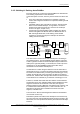
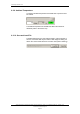
This view shows only the loop units and the cable segments. If a (or
several) Junction Box is included, this will not be shown in the
graphical view.
The cable segment will show only the closest cable information,
causing this cable characteristics and resistance (to be observed in
the view) not to be perfect. However the current flow and voltages at
each loop unit will be calculated correct.
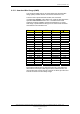
Note that it is assumed an internal resistance in the loop unit itself
caused by connections and the internal electronic switches, so that
the calculated voltage at the loop unit (internally) will be slightly
different from what is observed at the actual external connection
points.
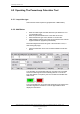
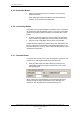
• Press the Graphical Button to view a graphical presentation of the
Power Loop. Two types of calculations are possible, “Break after
last loop unit” and “Break before first loop unit”.
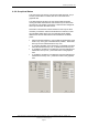
• To view the calculation in the first list box, in the Break Point area,
select “Break after last loop unit” or “Break before first loop unit”.
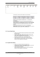
• To update the calculation in the Detector area and Cable area for
“Break after last loop unit” , press each button in the graphical
view.
• To update the calculation in the Detector area and Cable area for
“Break before first loop unit” , press each button in the graphical
view.
System Description, AutroSafe Integrated Fire & Gas Detection System, 116-P-ASAFE-IFG/XE Rev. B, 2005-10-27,
Autronica Fire and Security AS
Page 55