
User guide


Projecting Guidelines
5.6.5 Shielding & Earthing AutroFieldBus
Each unit that may be connected to AutroFieldBus has described the
local earthing requirements in their datasheet.
In the total system overview, some key issues needs to be taken care
of:
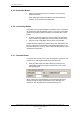
• There are no absolute requirements for shielding, however if
severe electromagnetic interference is expected, shielding should
be applied.
• If shielded cable is used, it should be continous. Care should be
taken to avoid earth/shield loops. As a guideline, connect the
shield to the B-side of the EAU-341 and not to the A-side (as
shown in the figure, chapter
4.2.4)
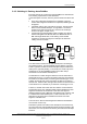
• If segments of the AutroFieldbus cable is isolated, as it will be
when including BSL-325 Booster, BSL-321 Multimode Fiber or
BSL-322 Single Mode Fiber, local earthing of the isolated
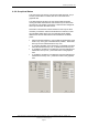
segments is required. See figure for example. We follow the
cabling counter-clockwise:
EAU-341
IE
AFB-A
AFB-A’
AFB-B
AFB-B’
AFB-CT’
AFB-CT
BSD-340
BSD-340
BSL-
325
BSL-
322
BSL-
322
Fiber
Junction
Box
1
2
3
The cable shield is referenced to earth at Earthpoint 2 according to
the guidelines above. Through the BSD-340 the shield is continued.
There’s a galvanic isolation in the Booster (BSL-325) that makes the
cable (on the right side) floating. To avoid this, the Center Tap of the
transformer of the AutroFieldBus (internal in the BSL-325) is
terminated to the local Earth at Earthpoint 3.
An alternative is to rather bring the reference from the other side of
the Booster across it, to continue the shield in that way. Note that the
bus needs to be referenced by connecting the CenterTap (pin 3 or 6)
to Earth. On the left side, this is ensured by the AFB-CT to Earth at
the EAU-341, while the BSL-325 right side needs to be tied to Earth or
to the reference of It’s left side, by for instance connecting pin 3 to 6.
Further on, the BSL-322 to BSL-322 also isolates. If there had been
several fiber jumps, each individual cable segment between the fiber
segments would have to be earthed. In this case, the segment
following passes through a BSD-340, the shield is kept continous and
it is referenced to earth at Earthpoint 1, close to the EAU-341. An
alternative to this would be to terminate at the other end of this
segment, at the BSL-322.
The main rule is: Ensure that all segment’s shield are terminated at
one end and one end only.
Dual Earth systems acts similar to the description of the PowerLoop,
as long as the inner Instrumental Earth shield is kept according to the
above rules, the outer protective shield may be terminated at multiple
locations.
System Description, AutroSafe Integrated Fire & Gas Detection System, 116-P-ASAFE-IFG/XE Rev. B, 2005-10-27,
Autronica Fire and Security AS
Page 49