
User guide

System Hardware
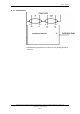
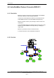
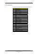
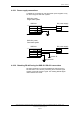
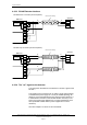
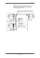
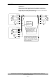
4.8.3.3 RS-485 Detector interface
5
6
7
8
15
17
18
19
20
27
28
16
AA
BB
A
B
ref
BSD-321
detector
5
6
7
8
15
17
18
19
20
27
28
16
AA
BB
A
B
ref
BSD-321
detector
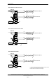
A
B
RS-485 cable shielding
RS-485 cable shielding
RS-485 earth
fault sensor
RS-485 earth
fault sensor
RS-485 branch connection (local loop-back):
RS-485 loop connection (remote loop-back):
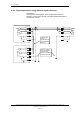
4.8.3.4 The ”ref” signal on the detector:
The ref signal on the detector is the detectors ”common” signal for the
RS-485.
This signal may be connected to IE (or earth in single earth systems),
to the detectors power supply 0V or it may be isolated (floating). All
detectors on the same RS-485 bus must have the same reference. It
is essential the connection to the RS-485 shield is done only in one
point in the system if the detectors are not 100% isolated from each
other (individual isolated detector power supplies and no earth
reference).
Also refer chapter
4.8.4 and 4.8.5 for more details.
System Description, AutroSafe Integrated Fire & Gas Detection System, 116-P-ASAFE-IFG/XE Rev. B, 2005-10-27,
Autronica Fire and Security AS
Page 34