
User guide

System Hardware
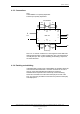
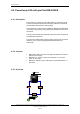
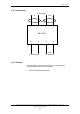
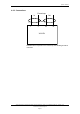
4.3.3 Connections
Note
AutroFieldBus is not polarity-dependent.
PowerLoop is polarity-dependent.
BSD-340
24V
Out In
1
2
6
A
+
A
- B+ B-
A
A
' B B'
7
IE
8
9 10
11 12 13
CT
16
CT
3
4
5
14 15
PowerLoop
Out In
A
utroFieldBus
PE
PE
IE
N
C
Note: “CT” is used as a reference in case segments of the AFB is left
floating when Boosters or Fibre modems are used. This termination is
normally left open. See “System Shielding and Earthing” chapter
5.6,
for further directions.
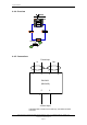
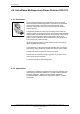
4.3.4 Earthing and shielding
If shielded cable is used for the AutroFieldBus, the shielding should be
continued around the BSD-340. It could be connected to CT both in
and out, see System Shielding and Earthing for reference.
Shielded cable is required for the PowerLoop, and the shielding
should be connected to the instrument earth (IE) at one end of the
loop. Any armouring should be connected to the protective earth (PE)
at multiple points.
System Description, AutroSafe Integrated Fire & Gas Detection System, 116-P-ASAFE-IFG/XE Rev. B, 2005-10-27,
Autronica Fire and Security AS
Page 19