
User guide

System Hardware
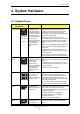
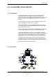
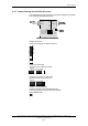
4.2.7 Jumper Settings for the EAU-321 board
The table below gives an overview of the jumper settings for the Serial
Port Communication Board EAU-321.
System Description, AutroSafe Integrated Fire & Gas Detection System, 116-P-ASAFE-IFG/XE Rev. B, 2005-10-27,
Autronica Fire and Security AS
Page 17
J5
J6
J7
Port 1
Port 2
I/O header
Port 1 and 2
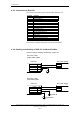
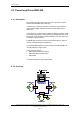
Jumpers J5 and J6:
J5 and J6 must be set to interrupt 2 and 5.
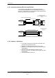
Jumpers J8 (interrupt)
J8 must be set to interrupt 7 and R.
Jumpers J9, J10 and J11 (interrupt)
All ports must be set to interrupt 7.
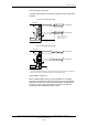
Jumper J7 (board address)
Jumper in position A and B must be set to In.
This setting applies to all communication boards.
Gives address 100h.
C
B
A
I/O header
Port 3 and 4
Serial Port Communication Board EAU-321
J8
J9
J10
J11
Address
jumpers
Port 4
Port 3
O header
3 and 4
J5
J6
J7
Port 1
Port 2
I/O header
Port 1 and 2
I/
Port
Serial Port Communication Board EAU-321
J8
J9
J10
J11
Address
jumpers
Port 4
Port 3
J5
J6
J7
Port 1
Port 2
I/O header
Port 1 and 2
J8
J9
J10
J11
Address
jumpers
Port 4
Port 3
Serial Port Communication Board EAU-321
TX
RX
CT
DC
DS
R1
1
2
3
4
5
6
TX
RX
CT
DC
DS
R1
1
2
3
4
5
6
15
12
11
10
7
6
5
4
3
2
R
15
12
11
10
7
6
5
4
3
2
R
15
12
11
10
7
6
5
4
3
2
R
15
12
11
10
7
6
5
4
3
2
R