Integrated Fire & Gas Detection System (IFG) System Description AutroSafe IFG Protecting life, environment and property... 116-P-ASAFE-IFG/XE Rev.
COPYRIGHT © This publication, or parts thereof, may not be reproduced in any form, by any method, for any purpose. Autronica Fire and Security AS and its subsidaries assume no responsibility for any errors that may appear in the publication, or for damages arising from the information in it. No information in this publication should be regarded as a warranty made by Autronica Fire and Security. The information in this publication may be updated without notice.
Table of Contents Table of Contents 1. Introduction.......................................................................4 1.1 1.2 1.3 About the Handbook ......................................................................... 4 The Reader ....................................................................................... 4 Reference Documentation ................................................................ 4 2. System Overview ..............................................................5 2.
Table of Contents 4.5 4.6 4.7 4.8 4.4.5 Connections ............................................................................ 22 4.4.6 Connection – current source................................................... 23 4.4.7 Connection – current sink ....................................................... 23 PowerLoop 4-20 mA Input Unit BN-342/EX...................................... 24 4.5.1 Description .............................................................................. 24 4.5.2 Versions ..
Table of Contents 6.2.10 Save and Load File ................................................................. 56 6.2.11 American Wire Gauge (AWG) ................................................ 57 7. Operation...........................................................................58 7.1 7.2 7.3 7.4 7.5 IFG-specific Menus ........................................................................... 58 Menu Structure – AutroSafe 3.5.0 - IFG ...........................................
Introduction 1. Introduction 1.1 About the Handbook This handbook is intended to provide supplementary information for the AutroSafe Integrated Fire & Gas System. 1.2 The Reader This supplementary documentation is intended to be used by trained service and technical personnel who are responsible for the configuration, installation, commissioning or operation of the AutroSafe Integrated Fire & Gas System. 1.
System Overview 2. System Overview 2.1 Definitions • Al_Com is the communication protocol for the AutroSafe Detection Loop. • AUTROLON is AutroSafe’s Local Operating Network. • AutroFieldBus is used to communicate with a BSD-340 interface and BSD-321. • PowerLoop is a two-wire bus capable of delivering 30VDC/ 100W connected in ring topology and is galvanically isolated from the rest of the system. The PowerLoop interfaces detectors and other loop units including a 4-20mA interface.
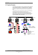
System Overview 2.2 System Example The illustration below depicts a system consisting of panels networked on an AUTROLON network. For compliance with C.E.N. regulations (EN-54), and for optimal safety, the AUTROLON must be installed as a ring loop. A maximum of 32 system units can be networked in this way. In the example, Al_Com communication is used to communicate with standard loop units and standard Ex-certified loop units.
IFG Functionality 3. IFG Functionality 3.1 Introduction This chapter covers some of the distinctions between AutroSafe functionality for Oil and Gas panels and standard AutroSafe panels. 3.2 Inhibit Point All loop input units can be inhibited. When one or several points are inhibited, the point(s) will not signal alarm to outputs. An inhibited point will however present an alarm, prealarm and early warning on all panels and AutroCom as usual. This includes panel buzzer, panel LEDs and panel LCD display.
IFG Functionality 3.5 Detection Zone faults and Point faults In standard AutroSafe, a point fault is presented as a detection zone (DZ) fault; the point in fault can be accessed via the panel menu. Oil and Gas panels can also be configured to present point faults as DZ faults. 3.
IFG Functionality 3.9 Support for Detectors Communicating on RS-485 (from SW 3.5.0) Release 3.5.0 (and future versions) supports the use of different detectors connected to the AutroFieldBus via the protocol-converter unit BSD-321. Supported detectors are: AutroPath, open-path gas detector SafeEye series 200/300, open-path gas detector AutroFlame CCTV flame detector and video switch Kidde Fenwal AnaLaser HSSD 3.
IFG Functionality 3.11 Local/External mode functionality Local/External functionality is selected via the AutroSafe configuration tool, as default, it is switched off (Local mode only). When switched on, the system toggles between the following modes: External mode: AutroSafe is operating together with an external system (with no communication faults or internal faults). The external system is able to control extinguishing agent activation.
System Hardware 4. System Hardware 4.1 System Panels System Units on AUTROLON Fire Alarm Control Panel Main Function BS-310G / 320G is a complete fire alarm control panel with full operating capabilities. The panel serves as a operating panel for BS310G (G2*) one or several defined 320G (G2*) operation zones. AL ARM Fire ext.. acktivated Silence buzzer Fire vent. activ. More Alarms Fire Brig. recvd.
System Hardware System Units on AUTROLON BV-320 Main Function information related to the defined operation zone(s). Description The display has space for 16 lines with 40 characters per line and shows detailed information on events. External 24 VDC Power is required. System Description, AutroSafe Integrated Fire & Gas Detection System, 116-P-ASAFE-IFG/XE Rev.
System Hardware 4.2 AutroFieldBus Driver EAU-341 4.2.1 Description The AutroFieldBus driver EAU-341 is a communication protocol converter between the AutroSafe IFG panel and the BSD-340 PowerLoop drivers and the BSD-321 RS-485 protocol converters. The EAU-341 provides a redundant field bus system with a ring loop topology. The AutroSafe panels can have one AutroFieldBus connected, and each AutroFieldBus can host up to 31 bus units.
System Hardware 4.2.3 Connections to EAU-341 All connections are made to plug-in screw terminals numbered 1-32.
System Hardware Power and earth connections If a single earth systems is used both IE and PE must be connected to the earth.
System Hardware 4.2.5 Connection between EAU-321 and EAU-341 Communication Cable XBA-055 is used between the Serial Communication Board EAU-321 and AutroFieldBus Driver Board EAU-341. An alternative is to use the break-out box (Autronica Fire and Security article no 7366-001.0020) AutroSafe EAU-321 via ribbon cable and termination block EAU-341 Panel communication Max 3m cable length EAU-341 PORT 0 25 26 27 3 5 9 Terminal block (AFS art no: 7366001.
System Hardware 4.2.7 Jumper Settings for the EAU-321 board The table below gives an overview of the jumper settings for the Serial Port Communication Board EAU-321. I/O header I/O Port 3 and 4 Port 4 J5 Port 1 Port 2 Port 3 I/O header Port 1 and 2 J6 J8 J9 J10 J11 J7 Address jumpers Serial Port Communication Board EAU-321 Jumpers J5 and J6: J5 and J6 must be set to interrupt 2 and 5.
System Hardware 4.3 PowerLoop Driver BSD-340 4.3.1 Description The PowerLoop Driver BSD-340 functions as a protocol converter between AutroFieldBus and PowerLoop. It consists of a PowerLoop interface for power and communication, and an AutroFieldBus interface towards an AutroFieldBus Driver (EAU-341). The PowerLoop is a two-wire bus capable of delivering 30VDC/ 100W connected in ring topology and is galvanically isolated from the rest of the system.
System Hardware 4.3.3 Connections Note AutroFieldBus is not polarity-dependent. PowerLoop is polarity-dependent. AutroFieldBus Out In A A' 11 12 1 B 13 CT B' 14 15 3 4 5 BSD-340 24V 2 IE 8 7 6 A+ A- 16 CT 9 PE PE IE 10 B+ BNC Out In PowerLoop Note: “CT” is used as a reference in case segments of the AFB is left floating when Boosters or Fibre modems are used. This termination is normally left open. See “System Shielding and Earthing” chapter 5.6, for further directions. 4.3.
System Hardware 4.3.5 Capacity / Limitations Each PowerLoop must be verified using the PowerLoop Calculator (ConfigTool). Generally, the following applies: • • • Maximum 15 detectors can be connected to each PowerLoop. May require forced cooling, disipates up to 30W when fully loaded. No branches allowed on PowerLoop or AutroFieldBus. The total power consumption to PowerLoop units, detectors and cable loss must be verified by the PowerLoop Calculator (part of the AutroSafe Configuration Tool).
System Hardware 4.4 PowerLoop 4-20 mA Input Unit BN-342 4.4.1 Description The PowerLoop 4-20mA Input Unit BN-342 is a general purpose PowerLoop interface designed for third party detectors connected to the AutroSafe Integrated Fire and Gas System. The PowerLoop is a two-wire power and signalling bus connected in ring topology and is galvanically isolated from the rest of the system. The unit communicates with AutroSafe using the PowerLoop protocol.
System Hardware 4.4.4 Overview AutroCom ALARM BS-320 General Alarm Fire Ext Activated Silence Buzzer Fire Vent Activated More Alarms Fire Brigade Msg Prewarning Early Warning Fault Silence Sounders Reset Power EAU-321 System Fault Function Disabled Test 1 2 3 4 5 6 7 8 9 C 0 EAU-341 ? Self Verify AUTROFIELDBUS BSD-340 BSD-340 BSD-340 PowerLoop Flame Detector BN-342 4-20mA Gas Detector 4.4.
System Hardware 4.4.6 Connection – current source 4.4.7 Connection – current sink System Description, AutroSafe Integrated Fire & Gas Detection System, 116-P-ASAFE-IFG/XE Rev.
System Hardware 4.5 PowerLoop 4-20 mA Input Unit BN-342/EX 4.5.1 Description The PowerLoop 4-20mA Input Unit BN-342/EX is a general purpose PowerLoop interface designed for third party detectors connected to the AutroSafe Interactive Fire Alarm System. The PowerLoop is a two-wire bus capable of delivering 30VDC/100W connected in ring topology and is galvanically isolated from the rest of the system. The unit communicates with AutroSafe using the PowerLoop protocol from BSD-340 Loop Driver.
System Hardware 4.5.4 Connections PowerLoop In Out + 1 - + 2 3 4 BN-342/EX 5 6 + 7 - 4-20mA input 8 - + 24V To detector 4.5.5 Earthing If shielded cable is used on the PowerLoop, the shield should be continued. Separate terminals are available. • See also datasheet for BN-342/EX. System Description, AutroSafe Integrated Fire & Gas Detection System, 116-P-ASAFE-IFG/XE Rev.
System Hardware 4.6 AutroFlame Multispectrum Flame Detector X33/1 PL 4.6.1 Description The AutroFlame Multispectrum Flame Detector X33/1 PL utilises advanced signal processing algorithms, supported by an embedded 32-bit microprocessor, to provide continuous protection in the presence of false alarm sources and environments with infrared radiation present.
System Hardware 4.6.3 Connections PowerLoop In Out + 1 3 + 18 15 X33/1PL Shielded cable is required for the PowerLoop, the shielding should be continued. System Description, AutroSafe Integrated Fire & Gas Detection System, 116-P-ASAFE-IFG/XE Rev.
System Hardware 4.7 AutroPoint Gas Detector HC300 PL The AutroPoint HC300 PL is a diffusion-based, infrared combustible gas detector that provides continuous, fixed monitoring of flammable hydrocarbon gases in concentrations from 0 to 100% Lower Explosive Limit (LEL). Ideally suited for protection of challenging on/offshore oil and gas facilities and other downstream hydrocarbon applications, the AutroPoint HC300 PL is certified for use in hazardous areas Zone 1 and Zone 2.
System Hardware 4.7.1 Connections 2 1 AutroPoint HC300 PL 3 Shielded cable is required for the PowerLoop, the shielding should be continued. System Description, AutroSafe Integrated Fire & Gas Detection System, 116-P-ASAFE-IFG/XE Rev.
System Hardware 4.8 AutroFieldBus Protocol Converter BSD-321 4.8.1 Description BSD-321 functions as a protocol converter between AutroFieldBus and various detectors communicating on RS-485. It consists of a serial interface for detector communication and an AutroFieldBus interface to an AutroFieldBus driver (EAU-341). BSD-321 provides a service port, MTA-style, used for service and maintenance. The AutroFieldBus address and desired protocol are set using rotary switches.
System Hardware 4.8.3 Connections All connections are made to plug-in screw terminals numbered 1-32.
System Hardware AFB cable with continuous shield BSD-321 A 1 2 3 4 9 10 11 12 AFB earth fault sensor Previous AFB unit A’ B Next AFB unit B’ * 31 IE AFB cable with discontinuous shield BSD-321 A 1 2 3 4 9 10 11 12 AFB earth fault sensor Previous AFB unit A’ B Next AFB unit B’ * 31 IE AFB cable without shield BSD-321 A 1 2 3 4 9 10 11 12 AFB earth fault sensor Previous AFB unit A’ B Next AFB unit B’ * 31 *: Connect if AFB earth fault detection is required.
System Hardware 4.8.3.1 Power supply connections The BSD-321 is intended for use with 24VDC power supplies. It may be used in single or dual earth systems. BSD-321 power, Single earth system BSD-321 +24 in 0V in IE PE DC power supply 29 30 31 32 +24V 0V BSD-321 power, Dual earth system BSD-321 +24 in 0V in IE PE DC power supply 29 30 31 32 +24V 0V System IE System PE 4.8.3.
System Hardware 4.8.3.3 RS-485 Detector interface RS-485 branch connection (local loop-back): RS-485 cable shielding detector BSD-321 RS-485 earth fault sensor 17 18 19 20 27 28 A A B B A B ref 5 6 7 8 15 16 RS-485 loop connection (remote loop-back): RS-485 cable shielding detector BSD-321 RS-485 earth fault sensor 17 18 19 20 27 28 5 6 7 8 15 16 A A B B A B ref A B 4.8.3.4 The ”ref” signal on the detector: The ref signal on the detector is the detectors ”common” signal for the RS-485.
System Hardware 4.8.3.5 Why loop-back? The BSD-321 requires a RS-485 loop-back connection. Loop-back is used to give increased system safety. While one channel on the BSD321 is transmitting, the other is receiving making it possible to verify that the internal operation of the BSD-321 is correct. By using RS-485 loop connection dual communication paths to the detectors are obtained in addition. Loop-back Loop-back of RS-485 can be done either locally on BSD-321 or remotely with loop to/from detector.
System Hardware 4.8.5 Typical applications using different signal references Application 1 The schematic drawing below shows an application where the reference is tied to the local earth. The cable shield is terminated at the BSD-321 end only.
System Hardware Application 2 The schematic drawing below shows an application where the reference is coupled to the detector’s reference. The RS-485 connection is floating at the BSD-321 side. The cable shield is terminated at the BSD-321 end only.
System Hardware Application 3 The schematic drawing below shows an application where the detector has common signal reference and Earth. The shield and signal reference is tied together at the same location by the detector only (the IE point at the ports are floating).
System Hardware 4.8.6 Port Isolation on RS-422 ports The schematic drawings show the RS-422 ports on the BSD-321. Each port is isolated from the rest of the electronics on the BSD-321 and has separate Instrument Earth per port. The signal reference of the driver / receiver is separated from Earth.
Projecting Guidelines 5. Projecting Guidelines 5.1 General Recommendations / Planning • Bear in mind future expansions when choosing cable dimensions, especially with regard to the PowerLoop. See Cable data on the next page and Cable Specifications in the System Specification Handbook, 116-P-ASAFE/XE. • Make sure that the PowerLoop is disabled during installation, service and maintenance. • No branches are allowed on the PowerLoop or AutroFieldBus.
Projecting Guidelines 5.2.
Projecting Guidelines 5.2.3 Cable data Standard loops PowerLoop Communications Loops - Maximum length Recommended cable: Screened cable; maximum loop reistance 50Ω, CSA 1.0mm2. Recommended cable: Screened cable; maximum loop resistance depends on load; CSA 1.5-2,5mm2 Larger installations may require up to 10mm2.The maximum cable length is 1000m. Recommended cable: CAT5 Maximum Cable Length resistance / dimensions capitance 50Ω / 0,5μF 2 x 0,75 18 1000m 2 x 1,5 15 2000m 2 x 2,5 13 3300m N. B.
Projecting Guidelines 5.2.4 Connectivity AutroCOM Modbus AutroCOM-compliant devices; AutroSafe devices. Provides connectivity with programmable logic systems for ventilation, process-control and distributed control systems. Provides SIL2-approved connectivity with programmble logic systems for ventilation, processcontrol and distributed control systems. ProfiBus/ProfiSafe 5.2.
Projecting Guidelines 5.3.2 Offshore platform systems Panels Smoke detectors Heat detectors Manual call-points Flame detectors Point gas-detectors Open-path gas-detectors Toxic-gas (H2S) detector 4 390 168 EX 28 117 106 155 67 24 5.3.3 Land-based petrochemical system Panels Smoke detectors Heat detectors Manual call-points Flame detectors Point gas-detectors Open-path gas-detectors 4 390 168 EX 28 117 106 155 67 5.
Projecting Guidelines 5.6 System Shielding and Earthing 5.6.1 Introduction The AutroSafe Integrated Fire and Gas System (IFG) has been designed to supply power and communications to advanced flame and gas detectors. The system is able to deliver up to 100W of power and uses a digital communications system, which modulates the PowerLoop at approximately 130kHz. The PowerLoop system also allows hundreds of metres of cable to be used between the loop driver and the field equipment.
Projecting Guidelines 5.6.3 Single Earth Systems – Power Loop Firstly, consider a Single Earth system for simplicity. 1) All PowerLoop cabling must be shielded Every segment of the PowerLoop cable has to be protected by a shield that effectively attenuates the radiated field from the cable. The shielding is required to avoid radiated emissions and hence crosstalk from one PowerLoop to any other. Armouring is normally not considered to be a sufficient shield.
Projecting Guidelines 4) Shield must be continuous The PowerLoop cable will be split in two segments, separated by field equipment including junction boxes or Loop Units. The shield must be continued through these separations. There must be no electrical connection to the local frame earth. In the following figure the junction boxes includes a strap / jumper to continue the shield between the cable segments (these straps / jumpers should be made of a suitable low-impedance cable).
Projecting Guidelines 5) Maximum cable length The PowerLoop Calculator will define the maximum length of each cable segment, this tool however determines length only from the power loss of the specified cable. The cable or wire capacitance will not affect the cable length as much as the resistive loss will restrict the power, not the communication. 5.6.4 Dual Earth Systems – Power Loop Some installations use both Instrument Earth (IE) and Protective Earth (PE) as two separate earthing paths.
Projecting Guidelines 5.6.5 Shielding & Earthing AutroFieldBus Each unit that may be connected to AutroFieldBus has described the local earthing requirements in their datasheet. In the total system overview, some key issues needs to be taken care of: • There are no absolute requirements for shielding, however if severe electromagnetic interference is expected, shielding should be applied. • If shielded cable is used, it should be continous. Care should be taken to avoid earth/shield loops.
Projecting Guidelines 5.6.6 Earth Fault Detection AutroFieldBus The enabling of the Earth Fault detection mechanism has been described earlier. It monitors the cable segment that is electrically connected to the EAU-341 loop driver. However, if the cable is interrupted electrically by a BSL-325 Booster or a Fibre modem, these segments may need additional Earth Fault Monitoring. This may be achieved by including a BSD-321 into this segment, and enable the Earth Fault Monitoring at this device.
PowerLoop Calculator Tool 6. PowerLoop Calculator Tool 6.1 Introduction The PowerLoop Calculator Tool is an integrated part of the AutroSafe Configuration Tool. The tool allows you to define and edit a Power Loop with a number of Loop Units. Based on the power consumption and the cable loss, the tool presents a go/no-go test to the user. The defined Power Loop can be saved for possible changes at a later stage.
PowerLoop Calculator Tool 6.2 Operating The PowerLoop Calculator Tool 6.2.1 Loop driver type Select first the PowerLoopDriver type (BSD-340 or BSD-340Ex) 6.2.2 Add Button • • • • Enter the cable length and cable dimension (the dimension is for your information only). Enter the specified resistive loss of the cable to be used. Select the detector type X33/1, BN-342 or Junction Box. If BN-342/EX is selected, also enter the actual load to the external equipment/detector (supplied by BN-342/EX).
PowerLoop Calculator Tool The Power In, Power Out and Cable Loss are calculated. Power In: Power supplied to the BSD-340, i. e. the total power consumption. Power Dissipation: To find out the total power/heat budget, the dissipated power from the BSD-340 inside the rack can be calculated. Simply calculate the power dissipation by Power In minus Power Out. Then add a comment in the Help about this field, to inform of the intention. Power Out: Power delivered to the loop from the BSD-340.
PowerLoop Calculator Tool 6.2.5 Delete Row Button • Select a row in the list box above to delete a row, then press Delete Row Button. When pressing the Delete Row Button, the tool automatically performs a new calculation and verification. 6.2.6 Load Config Button The Power Loop Calculator dialogue is modeless, thus it is possible to do configuration while the dialogue is open. In this way, the loop data (detectors in sequence) which is entered in the System View can be loaded.
PowerLoop Calculator Tool 6.2.8 Gra+phical Button This view shows only the loop units and the cable segments. If a (or several) Junction Box is included, this will not be shown in the graphical view. The cable segment will show only the closest cable information, causing this cable characteristics and resistance (to be observed in the view) not to be perfect. However the current flow and voltages at each loop unit will be calculated correct.
PowerLoop Calculator Tool 6.2.9 Ambient Temperature A maximum ambient temperature of the BSD-340 Loop Driver must be entered. The ambient temperature of the BSD-340 affects the maximum delivered power to the Power Loop. 6.2.10 Save and Load File The data entered from the user shall be saved to a file at request of the user, and same data may be read at a later stage for editing. All data in the current sheet will be lost if a file is read (make a warning).
PowerLoop Calculator Tool 6.2.11 American Wire Gauge (AWG) The conversion table puts into an exact relation the American Wire Gauge (AWG) number with the cross-section measured in mm2. The first column reports the AWG number, the second the corresponding diameter of the cable in mm, while the third reports the equivalent cross-section area in mm2. The table shows some examples of cables available, and their characteristics.
Operation 7. Operation 7.1 IFG-specific Menus The IFG-specific menus are included in the Show Status Menu (Inhibited Points) and Service Menu (Oil and Gas Commands). Main Menu Show Status Disable IFG-specific menus Enable System Service The menu structure on the following page shows the Integrated Fire and Gas Menu Structure for AutroSafe Release 3.5.0. System Description, AutroSafe Integrated Fire & Gas Detection System, 116-P-ASAFE-IFG/XE Rev.
Operation 7.2 Menu Structure – AutroSafe 3.5.0 - IFG Access Level > 2: Access by key. Access Level 3: Key and password restricted. Menu Structure – Ver. 3.5.
Operation 7.3 Show Status Menu / Oil&Gas Inhibited Points Show Status Fire Alarms Fire Warnings Faults Disablements Detection Zones Points Fire Alarm Devices Fire Alarm Routing Equipment Outputs Fault Warning Routing Equipment Immediate Output Actioning All Detection Zones in Test Oil & Gas Inhibited Points Activated Outputs Door Control Units Low Location Light Units Standard Control Units Other Outputs All System Description, AutroSafe Integrated Fire & Gas Detection System, 116-P-ASAFE-IFG/XE Rev.
Operation 7.3.1 Show Status – Oil & Gas Inhibited Points This menu gives detailed information on Oil & Gas Inhibited points. The example below describes how to view the current status of Oil and Gas Inhibited Points. Step 1 Actions to be taken Display Indication To enter the Main Menu, press MENU 19:23 Total: 3 1 SHOW STATUS 2 DISABLE 3 ENABLE 4 SYSTEM 5 SERVICE 2 To select SHOW STATUS, press 1.
Operation 7.4 Service Menu / Oil&Gas Commands Oil & Gas Commands Inhibit Point Cancel Inhibit Point Set Alarm Limits Get Measurement Values 7.4.1 Inhibit Point All loop input units can be inhibited. When one or several points are inhibited, the point(s) will not signal alarm to outputs. An inhibited point will however present an alarm, prealarm and early warning on all panels and AutroCom as usual. This includes panel buzzer, panel LEDs and panel LCD display.
Operation Step 3 Actions to be taken Display Indication To select OIL & GAS COMMANDS, press 4. SERVICE 19:23 OIL&GAS COMMANDS 1 INHIBIT POINT 2 CANCEL INHIBIT POINT 3 SET ALARM LIMITS 4 GET MEASUREMENT VALUES 4 To select INHIBIT POINT, press 1.
Operation 7.4.2 Cancel Inhibit Point The procedure describes how to cancel the inhibition of point(s). Step 1 Actions to be taken Display Indication To enter the Main Menu, press MENU 19:23 Total: 3 1 SHOW STATUS 2 DISABLE 3 ENABLE 4 SYSTEM 5 SERVICE 2 To select SERVICE, press 5. SERVICE 19:23 1 TEST 2 LOG 3 LOOP COMMANDS 4 OIL&GAS COMMANDS 3 To select OIL & GAS COMMANDS, press 4.
Operation Step Actions to be taken Display Indication 5 Use the keyboard to enter text into the input box OR ,- as shown in this example: SERVICE 19:23 CANC EL INHIBIT POINT 1ab12 1mc3 1mc6 To select a point, press then scroll downwards by pressing 9 YZ or move up again by pressing 6 PQR 6 To accept the selected point, press SERVICE 19:23 CANCEL INHIBIT POINT 1ab12 Execute cmd.
Operation 7.4.3 Set Alarm Limits The Set Alarm Limits command allows you to change a gas detector’s alarm limit for Low Alarm and High Alarm. Step 1 Actions to be taken Display Indication To enter the Main Menu, press MENU 19:23 Total: 3 1 SHOW STATUS 2 DISABLE 3 ENABLE 4 SYSTEM 5 SERVICE 2 To select SERVICE, press 5. SERVICE 19:23 1 TEST 2 LOG 3 LOOP COMMANDS 4 OIL&GAS COMMANDS 3 To select OIL & GAS COMMANDS, press 4.
Operation Step Actions to be taken Display Indication 5 Use the keyboard to enter text into the input box - SERVICE 19:23 SET ALAR M LIMITS OR , – as shown here Name: To select a point, press Gas Detector Interface Name: Type: then scroll downwards by pressing 9 YZ or move up again by pressing 6 PQR 6 To accept the selected point press, press SERVICE 19:23 SET ALAR M LIMITS Name: Gas Detector Interface Type: SimradGD10P IR Value: EU: Status: Lo w: H igh: No rmal 7 Use keyboard to
Operation 7.4.4 Get Measurement Values Step 1 Actions to be taken Display Indication To enter the Main Menu, press MENU 19:23 Total: 3 1 SHOW STATUS 2 DISABLE 3 ENABLE 4 SYSTEM 5 SERVICE 2 To select SERVICE, press 5. SERVICE 19:23 1 TEST 2 LOG 3 LOOP COMMANDS 4 OIL&GAS COMMANDS 3 To select OIL & GAS COMMANDS, press 4. SERVICE 19:23 OIL&GAS COMMANDS 1 INHIBIT POINT 2 CANCEL INHIBIT POINT 3 SET ALARM LIMITS 4 GET MEASUREMENT VALUES 4 To select GET MEASUREMENT VALUES, press 4.
Operation Step Actions to be taken Display Indication 5 Use the keyboard to enter text into the input box - SERVICE 19:23 GET MEASUREMENT VALUES OR , – as shown here Name: To select a point, press Gas Detector Interface Name: Type: then scroll downwards by pressing 9 YZ or move up again by pressing 6 PQR 6 To accept the selected point press, press SERVICE GET MEASUREMENT VALUES Name: Gas Detector Interface Type: SimradGD10P IR Value: 7 Use keyboard, press 8 Use keyboard, press 9
Operation 7.5 Show All Points In systems configured for IFG-functionality, the command Show all points is shown in the event of an alarm (Action Digit 1). Using this command will give a list of all points in alarm for all Detection Zones. FIRE ALARMS 19:23 Total: 4 1 Security office / HQ 2 Printer room / ADM 3 Copy / Fax room / ADM 4 Computer room / HQ 1: SHOW ALL POINTS The example above shows a situation where no detection zones are selected.
Troubleshooting 8. Troubleshooting 8.1.1 BSD-321 / EAU-341 Problem / Situation / Fault message Point Not responding. The system is sensitive to external noise / interference when, for example, lights are switched on or thermostats are activated. Only short messages are transmitted. Earth fault of AFB leads to communication faults. Possible Cause • The wrong protocol has been used for a detector.
Troubleshooting 8.1.
Troubleshooting Fault message: ----------------------------------------------------------------FAULT: Status Not accepted Type: AutroFieldBus Ground Fault detected Reported by ,, ----------------------------------------------------------------where: : Internal data : Internal data : Internal data To resolve fault: 1 - Remove ground fault 2 - Reset AutroSafe if fault is still present on panel --------------------------------------------------------------------------------
Troubleshooting Broken loop (open circuit): Fault message: ----------------------------------------------------------------Loop is open between points: (LSI) (LSI) Loop and panel (Loop driver address) (Panel switch setting) ----------------------------------------------------------------To resolve fault: 1 - Disable relevant loop 2 - Fix broken wire 3 - Enable relevant loop Loop short circuit: Fa
Troubleshooting BN-342 faults: Simrad GD10 configuration: Faulty power wiring or Detector without power or 4-20mA open circuit or faulty GD10 detector: NB: The GD10 will give 0mA for a 60 second period after powerup Fault message: ----------------------------------------------------------------FAULT: Status Not accepted Type: Point Sensor: Failure Reported by ,, ----------------------------------------------------------------where: : Internal data : Internal data : Internal d
Troubleshooting ----------------------------------------------------------------where: : Internal data : Internal data : Internal data To resolve fault: 1.1 - Replace detector OR 1.2 - Clean the detector optical parts according to SimradGD10 manual.
Troubleshooting ----------------------------------------------------------------FAULT: Status Not accepted Type: Point Sensor: Beam blocked Reported by ,, ----------------------------------------------------------------where: : Internal data : Internal data : Internal data To resolve fault: 1 - Remove items blocking the beam between transmitter and receiver 2 - Reset AutroSafe if fault is still present on panel ------------------------------------------------------------------
Troubleshooting To resolve fault: 1.1 - Replace faulty detector OR 1.2 - Repair detector according to Dräger XPtox manual.
Troubleshooting Status Not accepted Type: General protocol converter Ground fault detected Data Reported by ,, ----------------------------------------------------------------where: : : : : Internal Internal Internal Internal data data data data To resolve fault: 1 - Remove RS-485 ground fault. 2 - Reset AutroSafe if fault is still present on panel System Description, AutroSafe Integrated Fire & Gas Detection System, 116-P-ASAFE-IFG/XE Rev.
Reader’s Comments 9. Reader’s Comments Please help us to improve the quality of our documentation by returning your comments on this manual: Title: System Description, AutroSafe Integrated Fire & Gas Detection System, Ref. No.: 116-P-ASAFE-IFG/XE Rev. B, 2005-10-27 Your information on any inaccuracies or omissions (with page reference): Please turn the page System Description, AutroSafe Integrated Fire & Gas Detection System, 116-P-ASAFE-IFG/XE Rev.
Reader’s Comments Suggestions for improvements Thank you! We will investigate your comments promptly.
Reader’s Comments System Description, AutroSafe Integrated Fire & Gas Detection System, 116-P-ASAFE-IFG/XE Rev.
Autronica Fire and Security AS is an international company, based in Trondheim, Norway and has a world-wide sales and service network. For more than 40 years Autronica’s monitoring systems have been saving lives and preventing catastrophes on land and at sea. Autronica Fire and Security’s most important business area is fire detection & security. Autronica Fire and Security stands for preservation of environment, life and property.