
Specifications


Installation
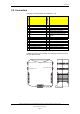
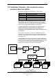
3.7.1 Jumper Settings — EAU-321
Port 4
Port 3
Port 1
Port 2
J5
J6
J7
J8
J9
J10
J11
Interfacing BU70 Display Units and BU100/BU101 Panels, AutroSafe Interactive Fire-Alarm System,
116-P-BSL337/EE, Rev. D, 2007-01-25,
Autronica Fire and Security AS
Page 15
Note that J5 determines port 1, and J6 determines port 2; in an
application where port 1 is in use by other equipment, then J6 should
be set as shown in the diagram, to allow connection of the BSL-337
interface.
Important: It is important that the physical port used and the port you
configure in the software corresponds to eachother.
TX
RX
CT
DC
DS
R1
1
2
3
4
5
6
TX
RX
CT
DC
DS
R1
1
2
3
4
5
6
C
B
A
15
12
11
10
7
6
5
4
3
2
R
15
12
11
10
7
6
5
4
3
2
R
15
12
11
10
7
6
5
4
3
2
R
15
12
11
10
7
6
5
4
3
2
R
20-19
1-2
2-1
19-20