Interfacing BU-70 Display Units and BU-100/BU-101 Panels AutroSafe BU-70 Interface BSL-337 Protecting life, environment and property... 116-P-BSL337/EE, Rev.
COPYRIGHT © This publication, or parts thereof, may not be reproduced in any form, by any method, for any purpose. Autronica Fire and Security AS and its subsidiaries assume no responsibility for any errors that may appear in the publication, or for damages arising from the information in it. No information in this publication should be regarded as a warranty made by Autronica Fire and Security. The information in this publication may be updated without notice.
Table of Contents Table of Contents 1. Introduction.......................................................................3 1.1 1.2 1.3 About the Handbook ......................................................................... 3 The Reader ....................................................................................... 3 Reference Documentation ................................................................ 3 2. Description .......................................................................
Table of Contents 4.2.3 Connections between the Current Loop/RS-232 Converter BSL-12/2 and BU-panels ....................................... 21 4.2.4 Mounting the Communication Line Splitter KDL-26B ............. 22 4.2.5 Connections between the Current Loop/RS-232 Converter and the Communication Line Splitter KDL-26B ..... 23 5. Configuring the AutroSafe System .................................24 5.1 5.2 Introduction........................................................................................
Introduction 1. Introduction 1.1 About the Handbook This handbook provides all necessary information required to interface BU-70 display units and BU-100/BU-101 parallel operation panels in the BS-100 system to AutroSafe Fire-detection systems. The BU-70 display units and BU-100/BU-101 parallel operation panels are referred to as BU-panels in this handbook.
Introduction Interfacing BU70 Display Units and BU100/BU101 Panels, AutroSafe Interactive Fire-Alarm System, 116-P-BSL337/EE, Rev.
Description 2. Description 2.1 Functional description / application 2.1.
Description 2.1.4 Printer support Note that the printer function on the BU-100 Parallel Operation Panel is not supported by using the BSL-337 interface. 2.2 Dimensions 120 45 99 114.5 Interfacing BU70 Display Units and BU100/BU101 Panels, AutroSafe Interactive Fire-Alarm System, 116-P-BSL337/EE, Rev.
Description 2.
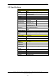
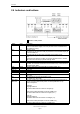
Description 2.4 Indicators and buttons / Language selection = Switch in ON position Name PWR Color Green FLT Red ST0 Yellow TX1 RX1 Green Red TX0 RX0 AFB TX AFB RX AFB ST1 S1 Green Red S2 BCD High / BCD Low Description Steady ON: Power OK Note: The LED flickers slightly once every second. This is an indication that the software is running. Pulsating: Fault The reason for the fault will normally be presented on the AutroSafe display as a fault from BSD-337.
Description 2.5 Connectors Function Terminal Terminal The plug-in screw terminals are numbered 1 – 32. 1 2 3 4 5 6 7 NC NC NC NC NC NC NC 17 18 19 20 21 22 23 8 9 10 11 12 13 14 15 16 NC NC NC NC NC TX, RS-232, Port 1 RX, RS-232, Port 1 Signal Reference Port 1 Instrument Earth Port 1 24 25 26 27 28 29 30 31 32 Function NC NC NC NC Service port, Tx. RS-232 Service port, Rx.
Installation 3. Installation 3.1 Hardware Requirements In order to interface BU-panels to an AutroSafe system, the following hardware is required: • AutroSafe Serial Communication Board EAU-321 — port 1 or 2 (See section 3.7 and 3.8).
Installation 3.3 Installation Overview - up to 16 BU-panels The following system blocks are referred to in this overview: EAU-321 AutroSafe Serial Communication Board in AutroSafe panel AutroSafe BU-70 Interface Current Loop/RS-232 Converter Display Unit Parallel Operation Panel BSL-337 BSL-12/2 BU-70 BU-100/BU-101 A maximum of 16 BU-panels can be connected to an AutroCom port.
Installation 3.4 Installation Overview - more than 16 BU-panels The following system blocks are referred to in this overview: EAU-321 BSL-337 BSL-12/2 BU-70 BU-100/BU-101 AutroSafe Serial Communication Board in AutroSafe panel.
Installation 3.
Installation 3.6 Standard Communication Parameters The BSL-337 is delivered from the factory containing the following communication parameters: • Port 0, to BU-70: 1200 baud • Port 1, to AutroSafe: 9600 baud, 8 databit, none parity, 1 stop bit 3.7 EAU-321 Serial-Port Communication Board The BSL-337 requires that the EAU-321 Serial-Port Communication Board is installed in the relevant AutroSafe panel; this allows the AutroSafe panel to communicate with BSL-337 using RS-232 on port 1 or 2.
Installation 3.7.
Installation 3.7.2 Termination by use of ribbon cable and standard screw terminal block J3 EAU-321 XGK-1/20-30 Port 1 and 2 20 19 9 (GND) 4 2 3 1 5 (Tx) 3 (Rx) Terminal Block The drawing shows an EAU-321 Port 1-connection. EAU-321 Port 2 may be used with connection terminals 13, 15 and 19. 3.7.3 Termination by use of cable XBA-055 Ribbon cable XBA-055 can be connected directly to the screw terminal on BSL-337.
Installation 3.8 RS-232 / Current Loop Communication 3.8.1 Overview The following system blocks are referred to in this overview: EAU-321 BSL-337 BU-100/BU-101 BU-70 BSL-12/2 AutroSafe Serial Communication Board AutroSafe BU-70 Interface Parallel Operation Panel Display Unit Current Loop/RS-232 Converter AutroSafe EAU-321 BSL-12/2 AutroCom BSL-337 RS-232 ASSP RS-232 RS-232 20mA 20mA Current Loop Current Loop Active transmitter Active receiver BU-70/ BU-100/101 1-16 24VDC 24VDC 3.8.
Installation 3.8.4 Maximum length of communication lines The recommended maximum length of the communication lines are as follows: RS-232 < 10 metres 20mA current loop < 1200 metres 3.8.5 Cable connections between BU-panels in the BS-100 system For information regarding cable connections between BU-panels (BU-70 display units and BU-100/BU-101 panels), refer to separate documentation (116-P-BU70/IE and 116-P-BU100/IE).
BSL_337 Installation 4. BSL_337 Installation The BSL-337 interface and RS-232/Current Loop Converter BSL-12/2 may be installed in one of two ways: internally or externally to the panel to which it is connected. 4.1 Two Types of Installation 4.1.1 Panel-Internal Installation Connect BSL-337 to the relevant port on the installed EAU-321 board; install the unit directly onto the panel-internal DIN-rail. The module is powered by the internal 24VDC power supply. 4.1.
BSL_337 Installation 4.2 Mounting and Connections Warning: If you connect the power supply to the wrong terminals, the unit may be damaged. Make sure that the BSL-337 and EAU-321 are connected to the AutroSafe power supply as described in this chapter. 4.2.1 General Connection Interfacing BU70 Display Units and BU100/BU101 Panels, AutroSafe Interactive Fire-Alarm System, 116-P-BSL337/EE, Rev.
BSL_337 Installation 4.2.2 Mounting the Current Loop/RS-232 Converter BSL-12/2 The Current Loop/RS-232 Converter BSL-12/2 has configurable inputs and outputs. The converter is delivered as a separate circuit board on a bracket prepared for mounting on a standard TS-35 rail. 77,5mm 55mm 135mm 4.2.3 Connections between the Current Loop/RS-232 Converter BSL-12/2 and BU-panels All cables are connected to screwterminals. If a system consists of more than one BU-panel, the BU-panels are interconnected.
BSL_337 Installation 4.2.4 Mounting the Communication Line Splitter KDL-26B The Communication Line Splitter KDL-26B is delivered as a separate circuit board on a bracket prepared for mounting on a standard TS-35 rail. Interfacing BU70 Display Units and BU100/BU101 Panels, AutroSafe Interactive Fire-Alarm System, 116-P-BSL337/EE, Rev.
BSL_337 Installation 4.2.5 Connections between the Current Loop/RS-232 Converter and the Communication Line Splitter KDL-26B The Communication Line Splitter KDL-26B is used to split the communication line from AutroSafe to BU-panels into 4 separate communication lines. A maximum of 10 BU-panels can be connected to one communication line (recommended limitation). The maximum number of BU-panels connected to each Communication Line Splitter is 16.
Configuring the AutroSafe System 5. Configuring the AutroSafe System 5.1 Introduction AL ARM Cable XJA-029 Cable XJA-033 Fire ext.. acktivated Silence buzzer Fire vent. activ. Fire Brig. recvd. More Alarms Power Prewarning Early warning Fault System fault Function disabled Test Silence sounders Reset 1 2 3 4 5 6 7 8 9 C 0 ? Self Verify AutroSafeConfig The procedure deals with the configuration of the AutroSafe Interactive Fire Alarm System.
Configuring the AutroSafe System • In the popup menu that appears, write the name of unit to be added, and state the number of units to be added (if necessary). BU-70 • Click on AutroCom Serial in the Entity window, then click on the Add button. • In the Tree View, click on the AutroCom Serial (in this example named AUTROCOM_SERIAL_Pager). Interfacing BU70 Display Units and BU100/BU101 Panels, AutroSafe Interactive Fire-Alarm System, 116-P-BSL337/EE, Rev.
Configuring the AutroSafe System • Select port number, 1 or 2. • Verify the parameter settings (baud rate to 9 600 baud, 8 bits, none parity, 1 stopbit). • Set the AutroCom Type to SERIAL_SLIDING_WINDOW in the drop-down box to the right. • From the Main Menu, click on View and select Operation View. • In the Tree View on the left side of the screen, click on the top level OZ (Operation Zone) – that is, if there are several Operation Zones in the AutroSafe system.
Configuring BSL_337 6. Configuring BSL_337 6.1 Settings on the Panel Front / Language selection = Switch in ON position The DIP-switches and rotary switches should be set as shown in the figure: S1.4 ON (RS-232 on port 1) S2.4 ON (RS-232 on port 0) Rotary switches: The switches are used to determine both the language (addresses 6064) and the the total number of BU-panels connected (addresses 0116).
Configuring BSL_337 6.3 Defining language and the total number of display units/panels Perform the procedure in the following sequence (first define the language, then the total number of BU-panels): Step 1: Defining language When defining the language, the rotary switches function as follows: BCD high: This switch determines the number of ten-digits (6). BCD low: This switch determines the number of one-digits (1-4).
Configuring BSL_337 Example: The language to be selected is English, and the total number of BU-panels are 16. • Set the switches according to English language (61): BCD high: 6, BCD low: 1 • Press the reset button on the BSL-337 interface (the LED will start flashing). • Set the switches according to a total of 16 BU-panels: BCD high: 1, BCD low: 3 • When the switches are set, press the reset button once more (the LED will change to a steady light). 6.
Testing BSL_337 7. Testing BSL_337 In order to verify that alarms, prealarms and faults are transmitted from the BSL-337 interface, complete a simple system setup as shown below. AutroSafe EAU-321 AutroCom BSL-337 RS-232 RS-232 24VDC BSL-12/2 20mA Current Loop BU-70 24VDC 24VDC Perform the following procedure: • Activate an alarm, prealarm and a fault on the AutroSafe system.
Testing the Final Installation 8. Testing the Final Installation When the installation is completed, verify that all BU-panels show alarms, prealarms and faults. When the power is turned ON, the following startup message will appear in the BU-70 display: S1200 01 (c)90AUT. Program Version Panel address 00-15 Baud rate: 1200 Baud When communication is established, the light in the display will go off and remain dark.
Appendix 9. Appendix 9.1 Datasheet RS-232/Current Loop Interface BSL-12/2 Interfacing BU70 Display Units and BU100/BU101 Panels, AutroSafe Interactive Fire-Alarm System, 116-P-BSL337/EE, Rev.
Appendix 9.2 Datasheet Communication Line Splitter KDL-26B Interfacing BU70 Display Units and BU100/BU101 Panels, AutroSafe Interactive Fire-Alarm System, 116-P-BSL337/EE, Rev.
Reader’s Comments 10. Reader’s Comments Please help us to improve the quality of our documentation by returning your comments on this manual: Title: Interfacing BU-70 Display Units and BU-100/BU-101 Panels, AutroSafe Interactive Fire-Alarm System Ref. No.: 116-P-BSL337/EE, Rev. D, 2007-01-25 Your information on any inaccuracies or omissions (with page reference): Please turn the page Interfacing BU70 Display Units and BU100/BU101 Panels, AutroSafe Interactive Fire-Alarm System, 116-P-BSL337/EE, Rev.
Reader’s Comments Suggestions for improvements Thank you! We will investigate your comments promptly.
Autronica Fire and Security AS is an international company, based in Trondheim, Norway, and has a world-wide sales and service network. For more than 40 years Autronica’s monitoring systems have been saving lives and preventing catastrophes on land and at sea. Autronica Fire and Security’s most important business area is fire detection and security. Autronica Fire and Security stands for protecting life, environment and property.