AUTOMATIC TRANSMISSION REMOTE STARTER SYSTEM AS-6105 SH Installation Guide Notice The manufacturer will accept no responsibility for any electrical damage resulting from improper installation of the product, be that either damage to the vehicle itself or to the Unit. This Unit must be installed by a certified technician using all safety devices supplied. Please note that this guide has been written for properly trained Autostart technicians, a certain level of skill and knowledge is therefore assumed.
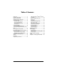
Table of Contents Introduction ..................................................... 3 Included in the Package ................................. 3 Before You Get Started…............................... 4 Installation Points To Remember ................... 4 Harness Description ....................................... 4 6-Pin Main Ignition Harness ....................... 5 5-Pin Secondary Harness........................... 5 12-Pin Accessories Harness ...................... 6 2-Pin Harness ...................
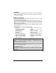
Introduction This Guide contains all information pertinent to the installation. Most (if not all) features are grouped in the User Guide and therefore, should you need information on a feature, you should refer to the User Guide Included in the Package Please review the Installation Guide before beginning the installation, particularly the Wiring Schematic and the Programming Options.
Before You Get Started… Ƈ On vehicles with a manual Transmission, always ensure that all Doors will get the Unit out of Ready Mode. Switch the wire used so that it is triggered by all Doors. Ƈ Make sure that the Parking Brake and Door Switch contacts work properly. Ƈ When working on a vehicle, always leave a window open. Ƈ Never leave the keys in the car. Leave them on a workbench with a window rolled down. Ƈ Remove courtesy light fuse, if possible, to prevent battery drain.
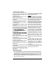
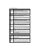
6-Pin Main Ignition Harness Wire Description Connect to the largest 12 V supply wire at the Ignition harness. Ensure that the OEM power wire is fused for more than 30 A. NOTE: certain new vehicles have no suitable 12 volts source at the RED A +12 V Battery IGNITION switch (the 12 Volt wire is too small to supply the necessary current). In this case, the fuse box, or the B+ connection on the battery is recommended. B PURPLE Connect to the Starter wire of the vehicle (at the IGNITION switch).
“under crank”. 3 GRAY (-) Hood Switch input Connect this wire to the Hood Pin-switch supplied. This input will disable or shut down the Remote Starter when the Hood is opened. It is also used for programming and therefore it is essential that it is installed. 4 ORANGE (+) Brake Switch input 5 YELLOW +12 V Parking Light output This wire must be connected to the Brake Light switch of the vehicle. The wire should be +12 V only while the Brake Pedal is pressed.
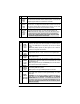
8 9 WHITE / ORANGE (–) Starter Kill output ORANGE N/A PURPLE (+) Siren or Horn output 10 WHITE (–) Ground out when running 11 GRAY (–) Negative Door input The unit is equipped with a selectable passive- or active-arming Starter Kill circuit that will immobilize the vehicle when the system is armed. This wire will provide a constant 500-mA negative output when the system is armed (locked by remote) or if remote started.
12 YELLOW (+) Glowplug Light input This positive input will monitor the Glow Plug Light in Diesel Mode: it will wait until the Glow Plug Light goes out to crank the Engine. Connect to the side of the Glow Plug Light that is positive when the Light is on. Note: In Diesel Mode there is a 18-sec. crank timing delay (or approximately 25-sec. if the run time is set to 30 min.): if the Glow Plug Light is still on after the delay expires, the Module will proceed to start the Engine.
2 output ON for a 30-second cycle and shuts off automatically unless the user presses LOCK and UNLOCK before the end of that cycle, at which point, the AUX2 output shuts off. x This output can also be used as Priority Door Unlock. Car Finder is enabled or disabled in the AUX 2 function programming. x 500 mA negative Parking Light output YELLOW Note: Ensure that the voltage does not vary when the dimmer control (-) Parking Light switch is turned up or down. If this is the case, it is not the right wire.
The Programming Assistance Button (A.k.a. PAB.) The PAB is located on the side of the Module. This push button mimics the Hood-Pin switch in order to avoid having to get out of the vehicle and pressing the Hood-Pin switch. The PAB will work only when the Hood is up. How to Program the Transmitter. 1. FLASH the Hood Pin Switch. Before the 20 seconds have passed, turn the Ignition Key to the IGNITION ON (RUN) position. Turn the IGNITION to OFF. 2.
The Module can only be programmed Function by Function. After selecting a Mode (from 1 to 3), you will be taken to the first Function of that Mode. After entering an Option number for Function 1, you will be automatically taken to Function 2, and so on; therefore, be ready to re-enter all option numbers for all functions of the Mode you are accessing. You may not skip Functions.
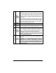
x All Doors unlock upon the 2nd , 4th, 6th … pressing of the UNLOCK button. Mode 2 *indicates default setting Function 1 – Home Valet Mode OPTION 1 Home Valet enabled OPTION 2* Home Valet disabled OPTION 3 Home Valet disabled Function 2 – Safe Start OPTION 1 OPTION 2* OPTION 3 Safe Start enabled Safe Start disabled Swap Start – increased safety mode: x To Start: press Lock and Unlock buttons simultaneously. x Press the START button to activate AUX 2.
OPTION 2* OPTION 3 Ignition Valet - ENABLED Ignition Valet - ENABLED Horn Honk / Siren Timing (Optional) 1. Make sure that Mode 3 Function 4 Option1 or Option 3 is activated. 2. FLASH the Hood Pin Switch Before the 20 seconds have passed, 3. Press and hold the Brake Pedal. x Press the START and UNLOCK buttons simultaneously on the Transmitter. x The Horn/Siren will sound 5 times. 4. Release the Brake Pedal. 5. To change the timing: a. To increase the Horn Honk/Siren by 3 ms, press the LOCK button. b.
Table 5 Multi-Speed Tach Programming No manual adjustments are necessary. However, you should go through the Tach programming procedure every time a new Unit is installed. 1. FLASH the Hood Pin Switch. 2. Press and hold the Brake Pedal. x Press the LOCK and UNLOCK buttons simultaneously on the Transmitter. x The Parking Lights will flash 4 times the Horn/Siren will sound 4 times (if programmed). x Release the Brake Pedal. 3. Start the vehicle and let it to reach regular Engine-idle speed. 4.
x x x 8. 9. 10. 11. Away. A medium “tap” should trigger the Warn Away. A hard “tap” should trigger the Alarm. All vehicles are different and therefore transmit shock level differently, if you are unable to set both zones to your satisfaction, referrer to p.12 (Function 4 – Shock Sense / Warn Away ) to disable the appropriate zone(s). When the Engine is running after remote start the Shock Sensor will not trigger an Alarm condition, although it will still produce warning chirps if Warn-away is enabled.
Caution! Do not use more than one of the three sets of jumper pins simultaneously. The relay output rating on this Unit is 25A max output. Defective OEM solenoid switches can sometimes draw up to 50 or 60A, causing the 30A fuse to blow. Using a digital voltmeter, check the Starter wire for amperage when vehicle is cranking. Ignition-Controlled Door Locks x x x x Ignition Lock disabled: turns OFF the Ignition Lock feature.
Safe Start (Child Safety Mode) (OFF by default.) Requires the user presses the within 3 seconds in order to start the vehicle. START button on the Transmitter twice If the Special Safe Start Mode is selected (SWAP Start): x To start the vehicle, press the LOCK and UNLOCK buttons simultaneously. x Pressing the START button triggers AUX2. START button becomes AUX2 trigger and the AUX2 button becomes the START trigger.
Disarmed Notification This feature will notify the user when the vehicle is left disarmed after Ignition is turned off, or when the Module is disarmed after being previously armed, the opening or closing of a Door will cause the Horn or the Siren to sound once after 10 sec. to warn the user that the vehicle was left unprotected. Pressing LOCK or UNLOCK will cancel this timer. Two-Stage Disarm When the Siren is sounding, pressing UNLOCK will stop the siren – but without unlocking or disarming the vehicle.
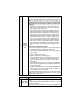
10 x = Alarm condition Intrusion Codes 1 x = Power-up Reset: Battery disconnected / reconnected or dead… 2 x = Doors intrusion 3 x = Shock Sense 4 x = Hood 5 x = Panic 6 x = Ignition Note: “x” stands for one flash of the Parking Lights Intrusion Codes via LED light If there has been an intrusion in the vehicle while it was locked and armed, the LED will provide an intrusion code corresponding to the type of the intrusion which took place. The LED intrusion codes are flashed in continuous loops.
Diagnostics - Parking Lights Flash Rate Flashes 1 2 3 4 5 6 8 10 1 – pause – 2 2 – pause – 2 ON solid ON 2 sec. ON 3 sec. ON 4 sec. ON 25 sec. Irregular Constant flashes up to 30 sec. P.20 Description Doors locked, Starter Kill armed. End of Run Time. TRUNK button pressed START signal received by the Module. Cold Weather Mode cancelled. Cannot start after maximum number of attempts is reached. Run Time cancelled. Remote start attempt cancelled by remote. Doors unlocked, Starter Kill disarmed.