
User guide

Spartan-6 FPGA Configuration User Guide www.xilinx.com 87
UG380 (v2.7) October 29, 2014
Configuration Sequence
After the configuration frames are loaded, the bitstream asserts the DESYNC command,
and then the START command instructs the device to enter the startup sequence. The
startup sequence is controlled by an eight-phase (phases 0–7) sequential state machine that
is clocked by the JTAG clock or any user clock defined by the BitGen -g StartupCLK
option. The startup sequencer performs the tasks outlined in Table 5-15.
The specific order of startup events (except for EOS assertion) is user-programmable
through BitGen options (refer to UG628
, Command Line Tools User Guide). Table 5-15 shows
the general sequence of events, although the specific phase for each of these startup events
is user-programmable (EOS is always asserted in the last phase). Refer to Chapter 2,
Configuration Interface Basics, for important startup option guidelines. By default, startup
events occur as shown in Table 5-16.
The startup sequence can be forced to wait for the DCMs and PLLs to lock with the
appropriate BitGen options. These options are typically set to prevent DONE and GWE
from being asserted (preventing device operation) before the DCMs and PLLs have locked.
Startup can wait for DCMs and PLLs by assigning the LCK_CYCLE option to a startup
phase. If this is not done, startup does not wait for any DCMs or PLLs. When the
LCK_CYCLE is set to a startup phase, the FPGA waits for all DCMs and PLLs to lock prior
to moving to the next phase of startup. To only wait for specific DCMs to lock, assign the
STARTUP_WAIT attribute to those instances. There is no corresponding attribute for PLLs.
When waiting for DCM and PLL lock, the GTS startup setting must be enabled on a phase
before LCK_CYCLE. Failing to do so results in the FPGA waiting for the clock components
indefinitely and never completing startup. For additional information on using the
LCK_CYCLE feature in master configuration modes, see Required Data Spacing between
MultiBoot Images, page 136.
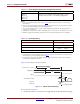
The DONE signal is released by the startup sequencer on the cycle indicated by the user,
but the startup sequencer does not proceed until the DONE pin actually sees a logic High.
The DONE pin is an open-drain bidirectional signal with an internal pull-up by default. By
releasing the DONE pin, the device simply stops driving a logic Low and the pin is weakly
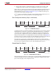
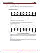
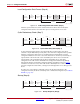
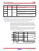
pulled High. Table 5-17 shows signals relating to the startup sequencer. Figure 5-12 shows
the waveforms relating to the startup sequencer.
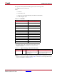
Table 5-15: User-Selectable Cycle of Startup Events
Phase Event
1–6 Wait for DCMs and PLLs to lock (optional)
1
–6Assert Global Write Enable (GWE), allowing RAMs and flip-flops to change state
1
–6 Negate Global 3-State (GTS), activating I/O
1
–6 Release DONE pin
7 Assert End Of Startup (EOS)
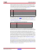
Table 5-16: Default BitGen Sequence of Startup Events
Phase Event
4 Release DONE pin
5 Negate GTS, activating I/O
6 Assert GWE, allowing RAMs and flip-flops to change state
7Assert EOS