
User guide

Spartan-6 FPGA Configuration User Guide www.xilinx.com 83
UG380 (v2.7) October 29, 2014
Configuration Sequence
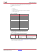
2. T
ICCK
is either T
SPIICCK
or T
BPIICCK
depending on whether the master SPI or BPI
configuration modes is used. In slave configuration modes, this is an input pin.
V
CCINT
, VCCO_2, and V
CCAUX
should rise monotonically within the specified ramp rate.
If this is not possible, configuration must be delayed by holding the INIT_B pin or the
PROGRAM_B pin Low (see Delaying Configuration, page 80) while the system power
reaches the recommended operating voltage.
VCCO_2, V
CCAUX
, and V
CCINT
are inputs to Power On Reset (POR). If either V
CCAUX
or
V
CCINT
dips below the operating minimum, POR might trigger again.
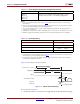
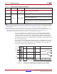
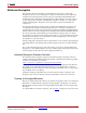
Clear Configuration Memory (Step 2, Initialization)
Configuration memory is cleared sequentially any time the device is powered up, after the
PROGRAM_B pin is pulsed Low, after the JTAG JPROGRAM instruction or the IPROG
command is used, or during a fallback retry configuration sequence. During this time,
I/Os are placed in a High-Z state except for the dedicated configuration and JTAG pins.
INIT_B is internally driven Low during initialization, then released after T
POR
(Figure 5-4)
for the power-up case, and T
PL
for other cases. If the INIT_B pin is held Low externally, the
device waits at this point in the initialization process until the pin is released.
The minimum Low pulse time for PROGRAM_B is defined by the T
PROGRAM
timing
parameter. The PROGRAM_B pin can be held active (Low) for as long as necessary, and the
device clears the configuration memory twice after PROGRAM_B is released.
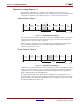
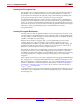
Sample Mode Pins (Step 3)
When the INIT_B pin transitions to High, the device samples the M[1:0] and begins driving
CCLK if in the Master modes. The device begins sampling the configuration data input
pins on the rising edge of the configuration clock.
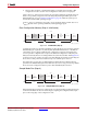
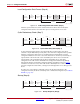
X-Ref Target - Figure 5-5
Figure 5-5: Initialization (Step 2)
Device
Power-Up
Sample Mode
Pins
Synchronization
Device ID
Check
CRC Check
Clear
Configuration
Memory
Startup
Sequence
Load
Configuration
Data
Start
Finish
UG380_c5_05_042909
Bitstream
Loading
Steps
123 45678
Setup
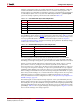
X-Ref Target - Figure 5-6
Figure 5-6: Sample Mode Pins (Step 3)
Device
Power-Up
Sample Mode
Pins
Synchronization
Device ID
Check
CRC Check
Clear
Configuration
Memory
Startup
Sequence
Load
Configuration
Data
Start
Finish
UG380_c5_06_042909
Bitstream
Loading
Steps
123 45678
Setup